
Install Instructions


Troubleshooting (continued)
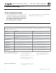
Check control fuses
ALWAYS check control fuses before replacing the
control or any major components (blower, etc.).
If one of these fuses is blown, it can prevent the
control or other components from operating.
1. Turn OFF power to boiler at external line switch. Then
remove the jacket door.
2. Locate fuses using Figure 93 .
3. Remove and inspect the two (2) fuses (items 1 and 2,
Figure 93 ).
4. If necessary, replace one or both of the fuses:
a. Low voltage circuit fuse is 3-amp fast-blow
(Littelfuse 0287003).
b. Line voltage circuit fuse is 12-amp fast-blow
(Littelfuse 0314012MXP or Bussman ABC-12-R).
Do not jumper either fuse or replace with any fuse
except as specifi ed. Failure to comply could result
in severe personal injury, death or substantial
property damage.
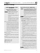
Checking temperature sensors
1. The boiler temperature sensors (fl ue, outdoor, return water,
supply water and system) are all resistance-type devices.
Figure 92 shows the correct value for the sensor at various
temperatures. For dual sensors, the temperature difference
between the sensors must be no more than 10°F.
2. Use the resistance values at 32°F, 60°F, 70°F and 212°F to
measure the sensor resistance at known temperatures (ice
point, room temperature and sea level boiling point). For
ice point and boiling point, insert the sensor in water at that
temperature. Use an ohmmeter to read resistance value.
3. To check whether the control is correctly sensing temperature,
you can use a resistance decade box. Connect the decade box
temporarily in place of a sensor and read the corresponding
temperature on the control display. The temperature should
be close to the value corresponding to the input resistance.
Figure 92
Sensor resistance values
Part number 550-100-191/0917
108
®
gas-fired water boiler — 70/110/155 Boiler Manual
Temp
(°F)
Sensor ohms
Temp
(°F)
Sensor ohms
Temp
(°F)
Sensor ohms
Min Max Min Max Min Max
32
34265 37871
90
8504 9399
150
2517 2782
40
27834 30764
100
6847 7568
160
2091 2311
50
21630 23907
110
5545 6129
170
1744 1928
60
16944 18727
120
4517 4992
180
1461 1615
70
13372 14780
130
3698 4088
190
1229 1359
80
10629 11747
140
3043 3364
200
1038 1147
Figure 93 Control fuses
2
Line Voltage
1
Low
Voltage