
Install Instructions


Troubleshooting
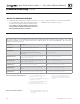
1. See Figure 91 for tools and kits recommended for troubleshooting
Evergreen® boilers.
2. Check for 120 VAC (minimum 102 VAC to maximum 132 VAC)
to boiler.
3. Check the control’s last three lockout histories. (Navigate to the
DIAGNOSTICS menus.)
a. See Figure 69, page 79 for navigation instructions and
Figure 75, page 84 for the complete Diagnostics menus.
b. In the DIAGNOSTICS menu, scroll down to PAST ERRORS
and press the enter key.
c. Record the fi rst four data records and then highlight the history
record you want to view.
d. Record the fault counts, (Control Faults, Ignition Retries,
Manual Reset Count, Auto Reset Count) and then highlight
the history record you want to view.
e. Follow information at the bottom of the screen to navigate
through your lockout histories.
Figure 91
Tools and kits needed for troubleshooting
Tool Purpose
#2 Phillips screwdriver
Multiple uses
3 mm Allen wrench
For removing igniter and fl ame sense screws
10 mm wrench
To remove heat exchanger cover plate
T20 long-handled Torx
driver
To remove burner screws
T25 Torx driver
To remove gas valve
5/16" Nut driver or
socket
To remove air baffl e
Multimeter
Measurements on sensors and electrical components
Manometer
(Inclined or digital)
Measure the INLET gas pressure to the boiler
Combustion analyzer
(Digital preferred)
Combustion testing and boiler adjustments
Contact thermometer
Checking surface temperatures of heat exchanger and
pipes
Maintenance kit
ALWAYS have this kit on hand when performing
maintenance in case replacement is required.
Check the following:
1. Make sure thermostat is calling for heat and contacts (including
appropriate zone controls) are closed. Check for 24 VAC between
thermostat wire nuts and ground.
2. Make sure all external limit controls are either installed (and closed)
or temporarily jumpered for testing.
3. Make sure that connectors to the control are securely plugged in
at module and originating control.
4. Gas pressures:
• Maximum: 13" (330 mm) w.c. with no fl ow (gas valve lockup
pressure).
• Minimum: must be no less than the minimum values given on
page 21 while operating on high fi re.
Before calling for troubleshooting assistance, fi ll in
the “
EVG Gas Data Collection Sheet” ( page 144 ).
Record the boiler size and CP number (located on the
right side exterior of the boiler jacket).
Part number 550-100-191/0917
107
®
gas-fired water boiler — 70/110/155 Boiler Manual
Failure to adhere to these
guidelines can result in severe
personal injury, death or
substantial property damage.
ELECTRICAL SHOCK HAZARD
TURN OFF ALL POWER TO THE BOILER WHEN
SERVICING
.
DO NOT JUMPER DEVICES
Never jumper (bypass) any device except for
momentary testing.
REINSTALL Jacket door
The boiler jacket door must be securely fastened to
the boiler to prevent boiler from drawing air from
inside the boiler room. This is particularly important
if the boiler is located in the same room as other
appliances. Failure to keep the jacket door securely
fastened could result in severe personal injury or
death.
BEFORE SERVICING or
MAKING CONNECTIONS —
ALWAYS TURN POWER OFF TO THE BOILER
TO PREVENT ELECTRICAL SURGES, WHICH
CAN DAMAGE BOILER COMPONENTS.
LABEL WIRES BEFORE
REMOVING
Label all wires prior to disconnection when servicing
controls. Wiring errors can cause improper and
dangerous operation.