
Install Instructions


Part number 550-100-191/0917
66
®
gas-fired water boiler — 70/110/155 Boiler Manual
Evergreen control setup
1. Set control parameters using the WIZARD option provided on
initial start-up or manually enter parameters using control menus
(see Figure 69, page 79 and following pages for information.)
2. See
Express setup
instructions beginning on page 72 for basic
systems and minimum settings required (using factory defaults).
3. This manual provides set-up information for a single boiler using
BASIC control setting options. See the EVG Advanced Manual for
single-boiler advanced settings and for all multiple boiler applications.
Boiler Model, Altitude and Fuel Type are critical settings.
Failure to set correctly could result in severe personal injury, death or
substantial property damage.
Temperature settings — You must ensure that the Evergreen control
is set for the proper water temperatures for the system. Excessive water
temperature can cause signifi cant property damage in some applications.
Multi-temperature systems — If the heating system includes circuits
that require lower temperature water (radiant slab circuits, for example)
as well as higher temperature circuits (DHW, fi nned tube baseboard,
etc.), it is recommended to protect low-temperature circuits with limit
controls that are wired to an Evergreen control external limit circuit.
Failure to provide regulation can result in substantial property damage.
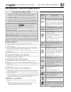
Control features
❏
Single or multiple boiler control (with lead boiler rotation).
❏
Graphic and robust text display for ease of operation monitoring and
troubleshooting.
❏
Three programmable priority assignments for up to three heat inputs.
❏
Preset operating parameters for typical heating systems, including target
temperatures, reset curves and circulator assignments.
❏
Integral outdoor reset option, with reset curves matched to the system
type selected.
❏
ModBus communications for external communication and monitoring.
❏
0-10VDC input modulation or remote target input.
❏
Four pump outputs, including 1 boiler pump output.
❏
Additional heat demand operation to call a second heat source to help
supply the energy required for heating.
❏
Advanced PI response to anticipate system needs.
❏
Flue temperature modifi er to target temperature.
❏
Modulation based on fl ue sensor and boiler/system supply/return sensors.
❏
Integral low water protection by monitoring heat exchanger temp.
❏
Dual temperature sensors on boiler outlet and fl ue, providing redundant
protection.
❏
Boiler is shipped with an outdoor sensor and strap on system supply and
return sensors.
❏
Blower speed modulation to control boiler fi ring rate.
❏
Alarm relay on error/fault for use with an audible safety.
❏
ZoneStacking
TM
– Uses All boiler inputs, not just the fi rst and last boilers, up
to 24 customizable inputs across boiler network (3 per unit, maximum of
8 boilers on the network).
❏
SmartSequencing
TM
–
Uses a low fi ring rate setting, called BASERATE
LOW, to keep boilers at a low fi ring rate, bringing on additional boilers at
reduced rate until all boilers are on if necessary. Boilers are then allowed
to modulate together as high as necessary to meet demand.
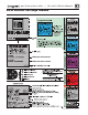
Sequence of operation
1. Figure 62 is a summary of the operating sequence for the Evergreen
control.
• The statuses shown appear in the display as the Evergreen control
cycles the boiler. See Figure 66, page 70 for screen shots.
• The display will fl ash red if a problem has been detected.
Figure 62 Control sequence of operation
Display
status
text
Control action
(also see Figure 66, page 70 )
POWER
UP
• Check the boiler model listed on the power-up
screen. If it is not correct, turn off the boiler.
See page 80 for instructions to change setting.
• When power is turned on, the screen lists sensors
that are detected. If any sensor is not listed, make
sure it is connected correctly. Turn off power
and restart.
Standby
• Standby - no calls for heat.
• Toggles through no dots, 1 dot, 2 dots, then 3
dots while in standby (wrench symbol will show
instead if maintenance is needed).
Blower
ON
• Call for heat detected.
• Display on with BLUE light (space heating) or
PURPLE light (DHW).
• Start min/max timers if more than one system
is calling - highest priority starts fi rst.
• Start circulators for this priority setup based
upon settings.
• Calculate target temp — If sensor temp is below
target temp, begin fi ring sequence.
• Blower to ignition speed for prepurge.
Ignition
• After prepurge times out, begin ignition cycle.
• Activate gas valve and ignition spark.
• Continue ignition spark for ignition period.
• Turn off spark and use electrode to check for
fl ame signal.
Space
Heating
• Flame detected.
• Release boiler to modulation.
• NOTE: If fl ame is not detected, the gas valve is
turned off, blower turns on (postpurge), and
control starts cycle again. After 5 failures, the
control waits 60 minutes, then tries again.
• If priority timer times out, switch to next priority
and start priority timer.
• If demand satisfi ed, go to postpurge.
DHW
Heating
• Flame detected.
• Release boiler to modulation.
• NOTE: If fl ame is not detected, the gas valve is
turned off, blower turns on (postpurge), and
control starts cycle again. After 5 failures, the
control waits 60 minutes, then tries again.
• If priority timer times out, switch to next priority
and start priority timer.
• If demand satisfi ed, go to postpurge.
Blower
OFF
• Demand satisfi ed (temperature reaches target
temperature or limit setting).
• Gas valve off.
• Blower to ignition speed for postpurge.
• Return to standby after purge.
Maintenance
• Display turns BLUE, toggling between graphic
screen and maintenance screen (occurs if
maintenance schedule timer times out).
• Will show during standby only.
• Boiler operates as normal.
Error/fault
• Display turns RED due to error or limit event.
• Flashing display means lockout condition.
WWSD
• Warm weather shut down - the boiler will not
be allowed to fi re on space heating if the outside
temperature is greater than the WWSD setting.
• DHW operation is not affected by WWSD.
Evergreen control operation