
Install Instructions

Part number 550-100-191/0917
13
®
gas-fired water boiler — 70/110/155 Boiler Manual
DO NOT install a relief valve with a pressure
higher than 30 PSIG
. This is the maximum
allowable relief valve setting for the boiler. Failure
to comply could prevent the relief valve from
operating as needed, resulting in possibility of
severe personal injury, death or substantial property
damage.
Use two wrenches when tightening any pipe
connection to the boiler
. Failure to prevent the
boiler pipes from turning could damage pipes or
heat exchanger, resulting in possible severe personal
injury, death or substantial property damage.
Hydrostatic pressure test
Pressure test the boiler before permanently attaching water or
gas piping or electrical supply.
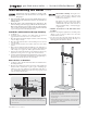
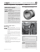
Install pipe fi ttings for relief valve and
P/T gauge
1. Install the reducer bushings (155 only), reducing tees, and
close nipples, shipped loose with the boiler, located and
oriented as shown in Figure 8, page 14 .
Boilers installed in locations with less than the
RECOMMENDED service clearances will need to
adjust piping layout to meet space requirements.
2. Apply pipe dope to all fi ttings sparingly.
DO NOT install the relief valve until after
the hydrostatic test. Temporarily install a ¾"
pipe plug in the relief valve location as directed in
these instructions. The plug must be removed after
the test.
Connect the relief valve ONLY on the
BOILER SUPPLY OUTLET, NOT the boiler
return. Connect the relief valve only as shown in
this manual. Ensure relief valve is located above
heat exchanger.
Failure to comply with the above could prevent
the relief valve from operating as needed, resulting
in possibility of severe personal injury, death or
substantial property damage.
3. Install the pressure/temperature gauge to the reducing tee as
shown in Figure 8, page 14 .
Install fi ttings and valves required for
hydrostatic testing
1. The following piping components (supplied by installer) are
required for the test confi guration:
a. Two shut-off valves (1" NPT on 70/110,
1¼" NPT on 155).
b. Two close nipples (1" NPT on 70/110,
1¼" NPT on 155).
c. ¾" NPT pipe plug.
2.
TEMPORARILY insert a ¾" NPT pipe plug in the relief valve
tapping. After the hydrostatic test, this plug must be removed
and the relief valve must be installed.
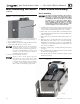
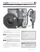
Fill and pressure test
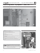
1. See Figure 9, page 14 for use with the following instructions.
2. CLOSE the boiler drain valve (item 11). Connect a hose to
fresh water supply and to the drain valve.
3. Place a bucket under the ends of the isolation valves (item 9
and 10) to catch water drippings.
4. CLOSE isolation valve item 10, then crack open the valve
slightly. Leave isolation valve item 9 open.
5. Slowly open the boiler drain valve (item 11) and fresh water
supply to fi ll boiler with water. The boiler and piping will fi ll
quickly because of the low water content.
6. When water begins to fl ow from bottom isolation valve (item
10), close the valve.
7. Continue fi lling until water fl ows from top isolation valve (item
9), then close the valve.
8. When pressure on the pressure/temperature gauge (item 4)
reaches at least 45 PSIG, but no higher than 55 PSIG, CLOSE
the boiler drain valve (item 11).
9. Hold at test pressure for 10 minutes.
Do not leave boiler unattended. A cold water fi ll
could expand and cause excessive pressure, resulting
in severe personal injury, death or substantial
property damage.
10. Make sure constant gauge pressure has been maintained
throughout test. Check for leaks. Repair if found.
Leaks must be repaired at once. Failure to
do so can damage boiler, resulting in substantial
property damage.
Do not use petroleum-based cleaning or sealing
compounds in boiler system. Gaskets and seals
in the system may be damaged. This can result in
substantial property damage.
Drain and remove fi ttings
1. Disconnect fi ll water hose from water source.
2. Drain boiler through drain valve
(item 11).
Use caution when releasing pressure from the boiler.
Rapid water fl ow could cause injury.
3. Remove hose after draining.
4. Remove nipples and valves unless they will remain for use in
the system piping.
5. Remove plug and install relief valve as specifi ed in the following
WARNING.
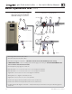
Remove plug from relief valve tee. Install the
relief valve in the ¾" tee. See page 43 or page 48
to install relief valve discharge piping. Failure to
install the boiler relief valve could result in severe
personal injury, death or substantial property
damage.
Boiler hydrostatic test