
Install Instructions

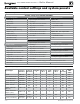


&IGURE $)!'./34)#3 menu navigation (see Figure 68, page 65 for access information)
DIAGNOSTIC menu
Part number 550-100-131/0715
– 78 –
™
GAS-FIRED WATER BOILER — Boiler Manual
-ENUS .EXTSCREEN .EXTSCREEN .EXTSCREEN .EXTSCREEN
Follow information at the bottom of each screen to navigate to next/previous screen or enter/save data
DIAGNOSTICS TEMPERATURES STATUS: ##########
BOILER OUT1: ###
ºF
BOILER OUT2: ###
ºF
BOILER IN: ###
ºF
SYSTEM SUPPLY: ###
ºF
SYSTEM RETURN: ###
ºF
FROM SENSOR: ######
FLUE 1: ###
ºF
FLUE 2: ###
ºF
OUTDOOR TEMP: ###
ºF
FROM SENSOR: ######
See following pages for details.
INPUTS STATUS: ##########
INPUT1: ######## (8-character system type)
INPUT2: ######## (8-character system type)
INPUT3: ######## (8-character system type)
0–10v: ##. #V
LINKED TO MASTER: ###
DEMAND OF MASTER: ###
MANUAL LIMIT: ######
AUTO LIMIT: ######
LOW WTR CUTOFF: ######
AIR P-SWITCH: ######
CLOSURE SWITCH: ######
BLOWER SPEED: ####RPM
FLAME SIGNAL: ###
See following pages for details.
OUTPUTS STATUS: ##########
GAS VALVE: ###
CIRC OUTPUT 1: ###
CIRC OUTPUT 2: ###
CIRC OUTPUT 3: ###
BOILER CIRC: ###
BLOWER SIGNAL: ###%
ADD’L HEAT DEMANDS: ###
ALARM: ###
See following pages for details.
RUNTIME BURNER TIME: ###HR
ROTATE TIME: ###DAYS
INPUT1 TIME: ###HR
INPUT2 TIME: ###HR
INPUT3 TIME: ###HR
NETWORK TIME: ###HR
IGNITION COUNT: ###
See following pages for details.
MASTER-SHADOW COMM
(shows on shadow boilers only)
Boiler ID: ############
Linked to Master: ###
Boilers on Network: #
Requested to Run: ###
Type: ######-##
Requested Mod Rate: ###
Max Boiler Temp: ###
ºF
Boiler ON Di: ##
ºF
Boiler OFF Di: ##
ºF
See following pages for details.
NETWORK BOILERS
(shows on master boilers only)
Shows ring rate, boiler temperature, active priority,
with system type and sequence order of all boilers on the
network.
See following pages for details.