
Install Instructions


Part number 550-100-131/0715
– 37 –
™
GAS-FIRED WATER BOILER — Boiler Manual
Use two wrenches when tightening water piping
at boiler, using one of the wrenches to prevent
the boiler interior piping from turning. Failure to
support the boiler piping connections to prevent
them from turning could cause damage to boiler
components.
General piping information
!DDITIONALCONTROLSIFREQUIRED
The control uses temperature sensors to provide
both high limit protection and modulating temper-
ature control. The control module also provides low
water protection by sensing the temperature of the
heat exchanger.
4HECONTROLSHIGHLIMITFUNCTION
REQUIRESMANUALRESET
. Some codes/jurisdictions
may require additional external controls for high
limit and/or low water cutoff protection.
!DDITIONALLIMITCONTROLS
Following standard industry practices, if installation is to com-
ply with ASME or Canadian requirements, an additional high
temperature limit may be needed. Consult local requirements
for other codes/standards to determine if needed.
1. Install a manual reset high temperature limit constructed to
prevent a temperature setting above 200°F in system supply
piping between boiler and isolation valve. (Note that the
Control operating limit function shuts the boiler down at
195°F, or lower if set to a lower value.)
-ULTITEMPERATURESYSTEMS — If the heating sys-
tem includes circuits that require lower temperature
water (radiant slab circuits, for example) as well as
higher temperature circuits, it is recommended to
protect low-temperature circuits with limit controls
that are wired to a Control external limit circuit
terminals.
2. See instructions beginning on page 50 for wiring information.
3. When using a manual reset limit control or wiring in the
manual reset circuit, preferably set Max. Boiler Temperature
or Supply Max. at least 20°F less than the external manual
reset limit (i.e., set control no higher than 180°F for a 200°F
external limit, for example).
3EPARATELOWWATERCUTOFF
1. A separate low water cutoff device is recommended when the
boiler is installed above piping level, and may be required by
certain state or local codes or insurance companies. Consult
local requirements to determine. See the NOTICE above
regarding the inherent protection provided by the Control
module. Low water cutoff is standard equipment with the
Evergreen
TM
boilers.
2. The Control’s integral protection is accepted in many jurisdic-
tions as meeting the requirement for low water protection.
See for details.
3. When required, use a low water cutoff designed for water
installations. Electrode probe-type is recommended.
See Replacement parts section at the end of this manual for
the Weil-McLain low water cut-off kit.
4. Purchase low water cutoff and install in a tee in the supply
piping above boiler.
5. See field wiring instructions beginning on page 50 for wiring
additional limit controls.
"ACKmOWPREVENTER
Use backflow preventer in the cold water supply piping if required
by local codes.
Boiler loop pipe sizing
"ASEBOARDCONVECTORSORCASTIRONRADIATORS/.,9
For residential space heating applications (other than radiant
heating or unit heaters) ONLY, you can use the sizing sugges-
tions in Figure 44.
&IGURE
Suggested pipe sizing for boiler loop
Use ATLEAST the -).)-5- pipe size shown in
Figure 44 on all boiler loop piping (connecting
boiler to and from the primary/secondary
connection).
5SEONLYPRIMARYSECONDARY
PIPING AS SHOWN
Failure to follow these
guidelines could result in system problems.
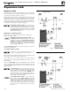
Install water piping
&IGURE Pressure drop through the Evergreen™ heat
exchanger
EVG 220 EVG 299/300 EVG 399
Flow Rate
(GPM)
Head Loss
(ft. w.c.)
Flow Rate
(GPM)
Head Loss
(ft. w.c.)
Flow Rate
(GPM)
Head Loss
(ft. w.c.)
12 0.0 18 0.3 24 0.3
14 0.1 22 0.6 28 0.7
16 0.2 28 1.2 32 1.1
18 0.2 32 1.7 36 1.6
20 0.3 36 2.1 40 2.2
22 0.5 – – 44 2.8
240.6––––
Model Boiler loop
EVG 220 1¼” or larger
EVG 299, 300 or 399 1½” or larger
Recommendations are based on a 25°F (EVG 220/299/300)
and 30°F (EVG 399) temp drop through the boiler.