
Install Instructions


Cleaning heat exchanger flue side
The boiler contains ceramic fiber materials. Use
care when handling these materials per instructions
on page 92 of this manual. Failure to comply could
result in severe personal injury.
Tools required
1. Allen wrench, 3 mm (T-wrench preferred).
2. 8 mm socket with 8-inch extension.
3. Metric wrench or socket, 10 mm.
4. Phillips head screwdriver, #2.
5. 5/16” socket or nut driver.
6. Torque wrench.
7. Putty knife.
Before proceeding:
1. Shut down the boiler:
a. Follow “To Turn Off Gas to Appliance” instructions on
boiler and Operating instructions.
b. Close the boiler manual gas valve.
2. Allow time for the boiler to cool to room temperature if it
has been firing.
3. Remove jacket front door by removing the two (2) latches at
the top of the jacket door.
4. Rotate and lift the jacket door away from the boiler to remove.
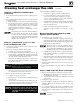
5. See Figure 103 (EVG 220 shown).
a. Remove the burner access panel (item 1) located on the
top of the boiler jacket by removing the screws (item 3).
b. Remove the air baffle (item 2) and screws (item 4) from
the jacket top as shown.
Remove and inspect the igniter
assembly
1. Carefully remove the ignition electrode assembly, following
the instructions in “Remove and inspect ignition electrode
assembly and wiring” on page 95.
2. Set ignition electrode assembly and new gasket aside for
later re-insertion.
Remove and inspect flame sense rod
assembly
1. Carefully remove the flame sense rod assembly, following the
instructions in See instructions on page 95 under “ Inspect
Flame Sense Rod”.
2. Set the flame sense rod with new gasket aside for later re-
insertion.
Remove, inspect and clean the burner
1. See Figure 106, page 113 (EVG 220 shown).
2. Use a Phillips screwdriver to remove the four (4) M4 screws
(item 10) that secure the burner access cover (item 4) to the
heat exchanger cover plate (item 6).
3. Remove the burner access cover (item 4) and the burner
(item 11).
Use caution when removing the burner to pull it
directly up and out. DO NOT angle the burner as
you remove it. Angling the burner could cause it to
strike the refractory, damaging the refractory and
causing fragments to fall into the heat exchanger.
Should this happen, a heat exchanger refractory
replacement kit must be installed and the heat ex-
changer must be thoroughly cleaned following the
procedures given in this manual and the refractory
replacement instructions.
4. Remove and discard the burner gasket (item 12). This gasket
is graphite and may pull apart or stick to the burner on re-
moval. Use a soft brush if necessary to remove residue. DO
NOT allow debris to drop into the heat exchanger. A new
gasket must be installed later when the burner is re-inserted.
5. Inspect the burner access cover seal (item 13). Discard and
use a new seal during re-assembly if the seal is damaged in
any way.
6. Inspect the interior of the burner. Brush and vacuum the
interior if needed to remove lint or sediment. Alternative
cleaning methods:
a. Blow air or nitrogen from the inside out.
b. Clean with a water spray from inside the burner.
7. Inspect the burner exterior. It must be in good condition,
with no visible damage.
8. Clean the under side of the burner flange (see item 15) with
a soft brush to remove any gasket fragments remaining.
9. Set the burner aside for re-insertion later.
&IGURE Remove the burner access panel and screws
(1 and 3) and air baffle and screws (2 and 4)
from the jacket top as shown
Part number 550-100-131/0715
– 109 –
™
GAS-FIRED WATER BOILER — Boiler Manual