
Advanced User Guide


Part number 550-100-160/0715
– 31 –
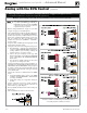
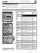
B. Zoning with CIRCULATORS, suggested applications
WMCR circulator zone controller plus DHW controlled by boiler, Optional DHW
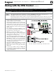
1. Review wiring information on page 21 (120 VAC out-
puts) and page 22 (24 VAC inputs).
2.
To shut down space heating during DHW operation
:
Provide and connect relay
R1
(120 VAC coil with NC
contact) to interrupt the zone controller’s ZC-ZR (120
VAC operating circuit).
a. This is required in all applications where the DHW
loop is piped in the system, not directly piped to
a boiler. Also, the boiler circulator must be set to
operate during DHW calls for system DHW ap-
plications.
b. For local DHW applications (DHW direct-piped to
a boiler), this relay is optional. Space heating pumps
will operate when called on by the zone controller,
but no heat will be delivered to the system — the
boiler circulator will not run during DHW heating.
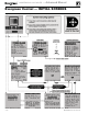
3. This application example provides domestic priority
by using the EVG control(s).
4. The configuration at right uses INPUT 2 on any boiler
for space heating with the call for heat coming from
the zone controller (X-X).
5. INPUT 1 is connected to a DHW aquastat.
6. This configuration applies to either a local demand
(direct-piped to a single boiler) or a network demand
(piped to the main system).
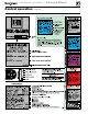
7. Suggested for space heating: Assign INPUT 2 to either
LOCAL PRIORITY 2 (direct) or NETWORK PRIOR-
ITY 2 (system). To set up the priority, choose the space
heating system type that matches the heating system
during the WIZARD setup or manually in the prior-
ity menu.
8. Suggested for DHW: Assign INPUT 1 to either LOCAL
PRIORITY 1 (direct) or NETWORK PRIORITY 1
(system). Wire the DHW circulator to OUTPUT 1. Set
the control for boiler pump ON if DHW is network
piped. Set the control for boiler pump OFF if DHW is
direct-piped to a boiler (local).
9. Use the factory default settings for DHW and for the
heating system type chosen, or change if needed. Fac-
tory defaults should work for other settings not listed
above.
P15, P11, and P2 are terminal strips on the EVG control
Relay
R1
, when used, is provided by installer
Zoning with the EVG Control
(continued)
CONDENSING GAS BOILER — Advanced Manual
™