
Advanced User Guide

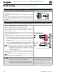


Part number 550-100-160/0715
– 27 –
CONDENSING GAS BOILER — Advanced Manual
™
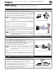
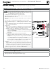
N. Proof of closure (flow switch and/or CAD)
– OPTIONAL
Jumper on Terminal Strip P7 (EVG control, bottom left of center)
1. A flow switch or combustion air damper (CAD) interlock can be configured
by clipping the jumper on terminal strip P7. Strip the jumper ends and wire
components as shown at right and in the wiring diagram (Figure 15, page 28).
2. No control settings are required when using a flow switch.
a. Each boiler is assumed to have its own flow switch, wired as shown at right.
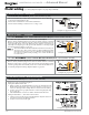
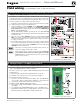
3. To configure the EVG control for a CAD interlock:
a. Assign any INPUT (recommend
INPUT 3) as a AUX PUMP/ OUTPUT
function. For multiple boiler applications, use any input on any boiler
in the network
. The example at right demonstrates using INPUT/OUT-
PUT 3
on the MASTER boiler.
b. For the AUX PUMP/ OUTPUT operating mode, select ANY BURNER
DEMAND. This ensures the damper will be activated any time any boiler
is called on to fire.
c. Wire the corresponding
OUTPUT (following recommendation, OUT-
PUT 3
) to provide 120 VAC to the damper motor when activated. Use
an isolation relay if damper motor requires another voltage or more than
2.2 amps on 120 VAC.
d. For a multiple boiler system, when any boiler is called on to fire, whether
for local or network demand, the combustion air damper will be powered
(120 VAC) from the assigned boiler
OUTPUT as shown at right (using
OUTPUT 3 on the master boiler).
The devices used must provide electrically isolated contacts, be-
cause the P7 jumper circuit carries 5 VDC.
Ensure that the wires are connected only as shown. The right side
of each jumper must connect only to the right side of other
jumpers
. Failure to comply will cause incorrect operation of the
proof of closure circuits.
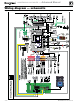
See Figure 15, page 28 for details
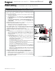
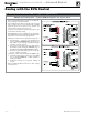
O. Multiple Boiler and BMS Connections
Terminal Strips P4 and P5 on Pump/Comm Board (control tray, left side)
1. The boiler control is capable of multiple boiler communication and control
of up to eight Evergreen boilers in one installation.
2. The boiler control is also capable of BMS (Building Management System)
communication.
3. See wiring at right and in the wiring diagram (Figure 15, page 28).
4. Use shielded 3-wire cable. Do not exceed 1,000 feet wire length.
5. Boiler to Boiler wiring connections
a. Connect 3-wire cable between Boiler-to-Boiler OUT (P4-GND,B2,A2)
on one boiler to Boiler-to-Boiler IN (P4-GND,B3,A3) on the next boiler.
b. Continue this wiring until all boilers are interconnected.
6. MODBUS to BMS (Building Management System)
a. The control is equipped with MODBUS communication to communicate
with a BMS.
b. Use terminal P5 (P5-BMSA,BMSB,GND) to wire to the BMS control.
c. If the BMS uses BACnet protocol, install a BACnet converter between the
BMS and the Evergreen MODBUS-to-BMS terminals (P5).
See Figure 15, page 28 for details
Field wiring (see wiring diagram, Figure 15, page 28)(continued)