
Advanced User Guide


Part number 550-100-160/0715
– 26 –
CONDENSING GAS BOILER — Advanced Manual
™
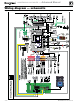
Field wiring (see wiring diagram, Figure 15, page 28)(continued)
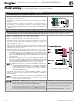
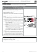
L. 0–10 VDC Remote MODULATION input – OPTIONAL
Terminal Block P15 #5 & #6 (EVG control module, left side)
Using an external multiple boiler controller — Remote modula-
tion using an external controller only works with each boiler set up
as a SINGLE boiler in the EVG Control setup.
1. See illustration at right and Figure 15, page 28 for details.
2. This illustration also shows how to connect TT or end switch contacts at
INPUT 2 and INPUT 3 for other uses.
3. This function can only be used with a single boiler, NOT for a boiler in a
network.
4. Note that using 0–10VDC input disables INPUT 1 as shown at right.
5. Remote modulation requires a 0–10VDC input signal at P15-4/5 as shown
at right.
a. The 0–10VDC input positive connection must be at terminal 6 and com-
mon connection at terminal 5.
6. Control setup:
a. Many options are available for configuring the control. The following is
a suggested setup that uses factory default settings as much as possible.
b. If DHW is required, use PRIORITY 1 to minimize setup steps.
s Connect the DHW aquastat to INPUT 2 or INPUT 3 and assign the
input used to PRIORITY 1.
s Verify that control settings are suitable for the application, changing
if necessary.
c. Use PRIORITY 2 for the system to be remote modulated.
s The factory default settings for this priority are best suited for space
heating.
s Assign INPUT 1 to the priority chosen. Accept all defaults for INPUT 1
— no changes should be necessary during the WIZARD.
s After the WIZARD has been completed, go to the ASSIGN INPUTS
menu for INPUT 1. Change SOURCE to 0–10V (default setting is
TT1). See page 50 for ASSIGN INPUTS menu information.
7. Operation:
a. The boiler comes on at 0.9VDC and turns off at 0.8VDC. 1 VDC = 10%
input. 10 VDC = 100% input. These voltage settings are not adjustable.
b. OUTPUT 1 (120 VAC) is activated and deactivated as the boiler is turned
on and off. This output is a good choice to operate the system pump.
8. NOTE: The EVG control can be configured to use either 0–10VDC for target
operation (see previous section) or modulation,
but not both.
See Figure 15, page 28 for details
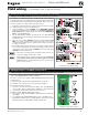
M. 120 VAC Power Receptacle
Located on boiler right side panel
1. Electrical rating is 2.0 amps max at 120 VAC.
2. This receptacle can be used to plug in a condensate pump.