
Advanced User Guide


Part number 550-100-160/0715
– 23 –
CONDENSING GAS BOILER — Advanced Manual
™
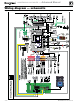
Field wiring (see wiring diagram, Figure 15, page 28)(continued)
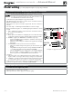
E. System supply and return temperature sensors – REQUIRED
Terminal Block P14 (EVG control module, left side)
1. Two strap-on temperature sensors are shipped with each boiler. Attach one
to the system supply piping and the other to the system return piping. For
piping larger than 5 inch diameter or nonmetallic piping, using immersion
sensors will provide faster response. See Evergreen boiler manual replace-
ment parts section for available immersion sensors.
Preferably, connect outdoor, system supply and system return sen-
sors to more than one boiler to provide redundancy. If one of the
sensors fails, the master boiler Evergreen control automatically look
for an available sensor.
2. Locate the supply sensor at least six pipe diameters, but no further than 3
feet, downstream from the boiler connection to the main to ensure adequate
mixing.
3. Supply sensor – wire between P14 #1 and #2 (common).
4. Return sensor – wire between P14 #3 and #2 (common).
5. Thermostat wire can be used to connect these sensors.
6. The Control compares the system return temperature with the system supply
temperature. Should the return temperature ever exceed the supply tempera-
ture, the Control knows there is likely a sensor failure and will report this
problem on the display.
All heating systems shown in this manual require the System Sup-
ply and Return sensors to be installed for proper control function.
System will not properly provide heat if sensors are not installed
according to these instructions.
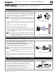
Strap to supply & return piping
See Figure 15, page 28 for details
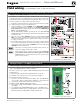
F. Outdoor temperature sensor – REQUIRED unless exempted
Terminal Block P10 (EVG control module, left side)
1. The control provides programmable options if using an outdoor tempera-
ture sensor. This sensor is supplied with the boiler.
2. The outdoor sensor must be installed unless specifically ex-
empted in the Energy Act statement on page 2.
3. Mount the outdoor sensor on an exterior wall, shielded from direct sunlight
or flow of heat or cooling from other sources.
Preferably, connect outdoor, system supply and system return sen-
sors to more than one boiler to provide redundancy. If one of the
sensors fails, the master boiler Evergreen control automatically look
for an available sensor.
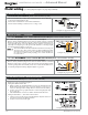
4. The wire outlet on the sensor must be oriented DOWN to prevent water
entry.
5. Connect the sensor leads to the terminal shown at right and in the wiring
diagrams (see Figure 15, page 28). Thermostat wire can be used to connect
the sensor.
See Figure 15, page 28 for details
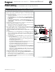
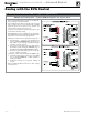
G. Additional heat demand contacts – OPTIONAL
Terminal Block P16 #6 & #7 (EVG control module, top left)
1. Each boiler’s control module can be set to activate another heat source using its
additional heat demand dry contacts through terminal block P16 pins 6 & 7.
2. Connect these terminals to call for heat from the other heat source.
3. Set the control to activate the heat demand contacts as needed.
4. The setup is done in the priority menu for the priority that will call for the
additional heat operation. See page 49 for details.
5. Contact electrical ratings: 24 VAC or less; 0.5 amp or less.
6. See “Add’l Heat Demand” on page 47 regarding which boilers may use this
function, depending on the priority being used.
See Figure 15, page 28 for details