
Advanced User Guide


Part number 550-100-160/0715
– 22 –
CONDENSING GAS BOILER — Advanced Manual
™
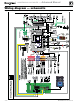
Field wiring (see wiring diagram, Figure 15, page 28)(continued)
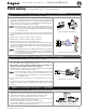
C. 120 VAC to Boiler Circulator – REQUIRED
Terminal Strip P8 on Pump/Comm Board (control tray, left side)
1. Provides 120 VAC to the boiler circulator at Pump/Comm Board P8 Terminals.
2. Terminals are: 1 (H), 2 (N), 3 (G).
3. Maximum load: 2.2 amps (use relay if circulator load is higher). See WARN-
ING above.
4. The boiler circulator (shipped loose with boiler) is used in the boiler loop
of the primary / secondary piping. Primary / secondary piping is required
to be used with the Evergreen boiler to ensure proper flow through the heat
exchanger.
See Figure 15, page 28 for details
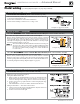
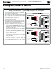
D. 24 VAC Inputs 1, 2 and 3 (tstats, end switches, etc.) – As needed for systems
Terminal Strip P11 (input 1) & Terminal Strip P15 (inputs 2 & 3) (EVG control module, left side)
1. Input 1 – Terminal Strip P11 – 4 & 5 (EVG control module)
2. Input 2 – Terminal Strip P15 – 1 & 2 (EVG control module)
3. Input 3 – Terminal Strip P15 – 3 & 4 (EVG control module)
4. These three inputs on each boiler can indicate a call for heat to the control
by means of a dry contact closure (thermostat, aqua
stat, or switch). (See
right and Figure 15, page 28).
5. Each control provides input/output pairs for up to three zones or three systems
(priorities). For multiple boiler applications, this is true for each boiler (for
eight boilers, total is 3 x 8 or 24).
6. For DHW applications, the aquastat can be connected to one of the three
input/output pairs. Wire the DHW circulator to the corresponding output.
a. For minimum setup steps, take advantage of the factory default settings.
Use LOCAL PRIORITY 1 for the DHW circuit if piped directly to the
boiler, or NETWORK PRIORITY 1 if the DHW circuit is located in the
system as a zone.
b. For DHW circuits piped as a zone in a system with a system pump, setup
the control to run AUX PUMP/ OUTPUT during DHW operation. This
can be done during the WIZARD setup process. Note that the input used
for AUX PUMP/OUTPUT cannot be used to accept a heat input.
DHW circuit in system — For high-demand DHW circuits, the con-
trol setting for MIN BOILERS must be set using the NETWORK 1
or NETWORK 2 priority menu after the WIZARD is completed
to ensure quick response to demand. See page 47 for a description
of the MIN BOILERS setting.
7. The default control setting uses each input (INPUT 1, INPUT 2, and IN-
PUT 3) to control its respective 120 VAC output (OUTPUT 1, OUTPUT 2,
and OUTPUT 3).
Use of 0–10VDC input for modulation disables INPUT 1 from
creating calls for heat. This function can only be set up on single
boilers. See page 26 for instructions.
See Figure 15, page 28 for details
Thermostats — DO NOT supply 24-volt power to the thermostat
circuits (Input1, Input2 and Input3 in
Figure 15, page 28
) or
attempt to supply 24 volts for any other application.
For thermostats that require a continuous 24-volt power
source, connect the common wire (“C”) to
P11
Pin 2
(see Fig-
ure 15, page 28)
.
Do NOT exceed total amp draw per thermostat.
Zone valves — If using 3-wire zone valves, use
relays to provide dry contacts to the Control ther-
mostat connections. The zone valve end switches
of 3-wire valves carry 24 VAC from the valve.
Thermostat anticipator setting — 0.1 amps.