
Advanced User Guide

Part number 550-100-160/0715
– 20 –
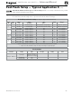
Field wiring (see wiring diagram, Figure 15, page 28)
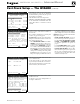
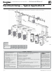
Figure 14 Field wiring overview (see Figure 15, page 28 and
Figure 16, page 29 for detailed schematic and ladder
wiring diagrams)
1 120 VAC knockout for power to boiler circulator terminals at
item 11.
2 For wiring to P12 – Low water cutoff kit (when used) wire
harness should be routed through this knockout with no other
wires. Provide strain relief and a seal at cabinet entry.
3 & 4 Two knockouts for low voltage wires to terminal strips at
items 9 and 10 (terminal strips P10, P11, P13, P14, P15 and
P16). These knockouts are provided with multi-hole cord
grips. Use if allowed by codes.
s4HERMOSTATAQUASTATLIMITDEVICEOUTDOORTEMPERATURE
sensor, system temperature sensor, and boiler communication
wiring should be mounted through the cord grip.
s-OUNTCORDGRIPTODESIREDLOWVOLTAGEKNOCKOUTANDSECURE
with a locknut before passing wire through cord grip.
s!FTERALLWIRESAREROUTEDTHROUGHCORDGRIPHOLESAND
secured to connecting terminals, hand tighten the nut on top
of the cord grip to seal any unused holes and grip the wires
tightly.
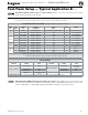
5, 6, 7 & 8 Four knockouts for 120 VAC wiring to power in (at
item 12) and three 120 VAC outputs on terminal strip (at
item 13)
9 Low voltage connection terminal strips are shipped loose with
boiler and must be plugged into receptacles on control module.
10 Low voltage terminal strips (P4 & P5) for connection of com-
munication cables (multiple boiler applications).
11 120 VAC terminal strip (P8) on Pump/Comm Board for boiler
circulator power.
12 120 VAC terminal strip (T1) for boiler power supply (15-amp
breaker unless larger capacity is required for outputs con-
nected on terminal strip P2, located at item 13).
13 120 VAC terminal strip (P2) for outputs to circulators or auxil-
iary devices.
14 Low voltage terminal strip P7: clip jumper to wire proof-of-
closure interlocks (combustion air damper, flow switch, etc.).
ELECTRICAL SHOCK HAZARD — For your safety, turn off
electrical power supply at service entrance panel before making
any electrical connections to avoid possible electric shock hazard.
Failure to do so can cause severe personal injury or death.
The installation must comply with National Electrical Code and
any other national, state, provincial or local codes or regulations.
In Canada, CSA C22.1 Canadian Electrical Code Part 1, and any
local codes.
Wiring must be N.E.C. Class 1. If original wiring as supplied with
boiler must be replaced, use only type 105 °C wire or equivalent.
Boiler must be electrically grounded as required by National
Electrical Code ANSI/NFPA 70 – latest edition.
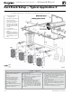
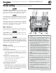
Wire entrances
Eight knockouts are provided in the top of the cabinet for line
and low voltage wiring. See Figure 14 for locations and functions.
Installer MUST use a strain relief through jacket knockouts.
Failure to do so can cause severe personal injury, death or sub-
stantial property damage.
Installer MUST SEAL all electrical entrances using a sealed strain
relief or a strain relief sealed with duct seal putty or silicone.
Sealing the entrances prevents water from entering the electrical
enclosure. Failure to seal entrances could result in severe personal
injury, death or substantial property damage.
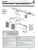
Wiring overview
See details on the following pages for the wiring connections
outlined below:
Required wiring connections
s 120 VAC power to boiler; 120 VAC power out to boiler cir-
culator; system supply and return temperature sensors; and
outdoor temperature sensor (unless exempt as described in
this manual).
Connections as needed by systems
s Thermostat, end switch or other inputs for call for heat.
s System zone circulators, valves, relays, etc.
s System circulator, when required.
s Low water cut-off (when required).
Optional wiring connections
s External limits; proof-of-closure interlocks (combustion air
damper, flow switch, etc.); 0–10VDC for target or modulation
control; remote alarm; additional heat demand contact; and
communication cables for boiler networking and/or building
management system interface (MODBUS).
CONDENSING GAS BOILER — Advanced Manual
™