
Advanced User Guide

Part number 550-100-160/0715
– 16 –
CONDENSING GAS BOILER — Advanced Manual
™
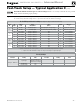
Fast-Track Setup — Typical Application B
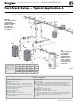
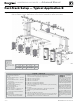
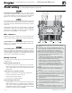
Figure 10 Typical Application B — Piping layout — typical piping for multiple Evergreen boilers, with DHW storage
heaters (4-boiler system) (adjust boiler connections as required for other boiler models)
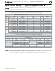
Legend — Figure 10
1 Flow/check or spring check valve.
2 Isolation valves (when used).
3 Caps.
4 Easy-Fit® Manifold (supply) — layout and
size per page 7.
5 Easy-Fit® Manifold (return) — layout and
size per page 7.
6 System circulator (not used if system is
circulator zoned).
7 Expansion tank (diaphragm type).
8 System air eliminator.
9 System automatic air vent.
12 Boiler drain valve
13 Cold water supply (per applicable codes).
17 Boiler circulator — circulates water
between boiler and Easy-Fit® Manifolds.
18 System supply.
19 System return.
20 Boiler relief valve and discharge piping,
installed per Evergreen boiler manual.
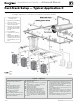
21 Indirect-fired storage water heaters (Weil-McLain Aqua Plus Line shown) —
Example is shown with each water heater having its own circulator. Alternate:
reverse-return boiler-side piping using a single circulator.
22 DHW boiler water supply, typical.
23 DHW boiler water return, typical.
24 DHW boiler-side circulators.
25 DHW boiler-side supply Easy-Fit® Manifold.
26 DHW boiler-side return Easy-Fit® Manifold.
27 Flow/check or spring check valves (to prevent induced or gravity flow in heating
system or DHW piping).
28 Check valve.
29 See water heater manual for DHW piping — The boiler-side piping in this
example uses a separate circulator for each DHW tank.
31 Unions.
32 Drain valves for DHW boiler water piping.
33
Strap system supply and return sensors to lines as shown, at least 6 pipe diameters
(but no more than 3 feet) from boiler connection tees. For redundancy, you can
install multiple sensors, each connected to a different boiler.
This piping is
suggested only.
The layout above can be controlled
with the boiler control’s multi-
boiler function, DHW priority or
by an external control that provides
multiple boiler heating and DHW
priorities. This will provide domes-
tic priority by disabling the heating
system circulator any time there is
a DHW call for heat. The boiler
circulators, item 17, must operate
on any call for heat, whether heat-
ing system or DHW. Offset the
DHW boiler-side supply and return
manifolds as shown so the total run
of pipe and fittings to each of the
water heaters is approximately
equal.
Suggested DHW
boiler-side pipe
sizing
(for max 0.04
feet head loss per foot of
total equivalent length,
TEL)
Flow rate Size Flow rate Size
1 – 3.9 gpm ¾ 24 – 45 gpm 2
3.9 – 7.1 gpm 1 45 – 75 gpm 2½
7.1 – 16 gpm 1¼ 75 - 140 gpm 3
16 – 24 gpm 1½ 140 – 290 gpm 4
Blr 1
Blr 2
Blr 3
Blr 4
DHW1
DHW2
DHW3