™ CONDENSING GAS BOILER 220/299/300/399 Advanced Manual Multiple boiler installation & settings + Single boiler advanced settings This manual must only be used by a qualified heating installer/service technician. Read all instructions, including this manual and all other information shipped with the boiler, before installing. Perform steps in the order given. Failure to comply could result in severe personal injury, death or substantial property damage.
™ CONDENSING GAS BOILER — Advanced Manual Contents Evergreen Control — Advanced mode . . . . . . . 3 Multiple boiler installations . . . . . . . . . . . . . 6 Fast-Track Setup — Requirements by Boiler . . . . 9 Fast-Track Setup — Steps . . . . . . . . . . . . . 10 Fast-Track Setup — The WIZARD . . . . . . . . . 11 Fast-Track Setup — Typical Application A . . . . 14 Fast-Track Setup — Typical Application B . . . . 16 Fast-Track Setup — Typical Application C . . . .
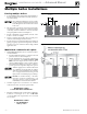
™ CONDENSING GAS BOILER — Advanced Manual Evergreen Control — Advanced mode Multiple Boiler (Network) Features: Evergreen control setup (see next page for explanation of Priorities) s Create a network of up to 8 boilers using built-in controls. s Master boiler controls the modulation and sequencing of boilers on the network to achieve desired system supply temperature.
™ CONDENSING GAS BOILER — Advanced Manual Evergreen Control — ADVANCED mode (continued) EVG control Priorities & Input/Outputs Multiple boiler operation s s The Evergreen boiler has an auto detection feature for multiple boiler networks. The Master will automatically detect the presence of the other boilers wired to the network. s There will be a 30 second to 1 minute period until the Master may see the shadow boilers. s Each shadow boiler must be assigned a network address, from 2 through 8.
™ CONDENSING GAS BOILER — Advanced Manual Evergreen Control — ADVANCED mode SUPPLY MIN 1. SUPPLY MIN should equal the desired minimum supply water temperature for the system. 2. This could be set as low as 70°F, which would supply “zero heat” when outdoor temperature is 70°F, because supply water temp would equal room temp. 3. See examples in Figure 1. (continued) Figure 1 Outdoor reset operation Figure 2 Remote target operation OD RESET MAX 1.
™ CONDENSING GAS BOILER — Advanced Manual Multiple boiler installations Placing multiple boilers Figure 3 1. Locate multiple boilers with spacings shown in Figure 3. Provide the indicated clearances around boilers for access and servicing. 2. 3. 4. 5. If recommended dimensions are not possible, provide at least the minimum clearances given in the Evergreen boiler manual. Also follow local codes.
™ CONDENSING GAS BOILER — Advanced Manual Multiple boiler installations Easy-Fit® piping installation 1. Main header and Easy-Fit® Manifold pipe sizing. a. Size system piping as required for the flow. b. Install tees or crosses in the system piping for Easy-Fit® manifolds as shown in Figure 5 or Figure 6. Size manifolds to handle total connected boiler output as shown. 2. Provide connections in main header for Easy-Fit® manifolds as close as possible to the midpoint of multiple boilers. a.
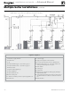
™ CONDENSING GAS BOILER — Advanced Manual Multiple boiler installations Figure 7 (continued) Piping schematic — typical piping for multiple Evergreen boilers, using Weil-McLain Easy-Fit manifolds (adjust boiler connections as required for other boiler models) Legend — Figure 7 1 Flow/check or spring check valve. 13 Cold water supply. 2 Isolation valves. 14 Supply water temperature control (when used). 3 Cap. 15 Low water cutoff (when used) (place above primary header).
™ CONDENSING GAS BOILER — Advanced Manual Fast-Track Setup — Requirements by Boiler Fast-Track Setup s Single boilers: PRIORITY 1, PRIORITY 2, PRIORITY 3. Evergreen control Fast-Track Setup takes advantage of the Evergreen control WIZARD to provide the shortest possible method to set up the control.
™ CONDENSING GAS BOILER — Advanced Manual Fast-Track Setup — Steps The WIZARD must be used when using the Fast-Track Setup procedure. This is necessary to ensure that all required settings are made. In addition, all instructions in the Evergreen boiler manual must be followed completely. Failure to comply could result in severe personal injury, death or substantial property damage.
™ CONDENSING GAS BOILER — Advanced Manual Fast-Track Setup — The WIZARD s The WIZARD is available only on initial setup of the boiler. It cannot be accessed later. If the WIZARD is accidentally by-passed, follow navigation sequences shown on page 40 and page 41. Select RESET FACTORY DEFAULTS on the Boiler Settings menu. Follow screen directions. Boiler setup must then be started over from the beginning.
CONDENSING GAS BOILER ™ — Advanced Manual Fast-Track Setup — The WIZARD (continued) If TARGET ADJUST = ODT EVERGRE EN WI # # OF ## SY S T EM T Y P E : # # T A R G E T MO D S E N BO I L TARGE T AD JUST : : SUPP L Y MA X SU OD OD BO RU RU MA P P R R OS N N X L E E T B A O Y M I N S E T MA X S E T M I N T I ME : O I L E R P U X / P UMP N T I ME : B A C K S E L E C T ZARD ###### SOR : ER OUT ODT # # # ° F : : : # # # # UMP ? OU T # If TARGET ADJUST = 0–10V EVERGRE EN WI Z # # OF ## SY S T EM T Y P E
™ CONDENSING GAS BOILER — Advanced Manual Fast-Track Setup — The WIZARD (continued) ▼ ▼ EVERGRE EN # # OF WI ZARD ## L OC A L - N E TWO R K SW I T C H I N G T I ME S NE T NE T LP 2 X ON T I ME : # # #M | N X ON ON T I ME : T I ME : # # #M # # #M | N ON T I ME : # # #M ▼ MA | ▼ M I MA | ▼ M I ▼ L P 1 NE X T S T E P B A C K S E L E C T EVERGRE EN # # OF BO I L E R SE QU E NC E L E AD BO I I NCR RO T A T FORC E L E NE X T H E L P E D I T WI ZARD ## S E QU E NC I NG T Y P E : SMA
™ CONDENSING GAS BOILER — Advanced Manual Fast-Track Setup — Typical Application A Figure 8 Typical Application A — Piping layout — typical piping for multiple Evergreen boilers, using Weil-McLain Easy-Fit manifolds (2-boiler system) (adjust boiler connections as required for other boiler models) NOTICE: This method does not provided DHW redundancy. DHW can only be supplied when Boiler 2 is operational.
™ CONDENSING GAS BOILER — Advanced Manual Fast-Track Setup — Typical Application A (cont.) Boiler Model, Altitude and Fuel Type are critical settings. Failure to set correctly could result in severe personal injury, death or substantial property damage.
™ CONDENSING GAS BOILER — Advanced Manual Fast-Track Setup — Typical Application B Figure 10 Typical Application B — Piping layout — typical piping for multiple Evergreen boilers, with DHW storage heaters (4-boiler system) (adjust boiler connections as required for other boiler models) Blr 1 Blr 2 Blr 3 Blr 4 Suggested DHW boiler-side pipe sizing (for max 0.04 feet head loss per foot of total equivalent length, TEL) Flow rate Size Flow rate Size 1 – 3.9 gpm ¾ 24 – 45 gpm 2 3.9 – 7.
™ CONDENSING GAS BOILER — Advanced Manual Fast-Track Setup — Typical Application B (cont.) Boiler Model, Altitude and Fuel Type are critical settings. Failure to set correctly could result in severe personal injury, death or substantial property damage.
™ CONDENSING GAS BOILER — Advanced Manual Fast-Track Setup — Typical Application C Figure 12 Typical Application C — Piping layout — typical piping for multiple Evergreen boilers, using isolation exchanger (adjust boiler connections as required for other boiler models) Use isolation heat exchanger for: 1. Large volume systems with high mineral content in water. 2. Systems exposed to untreated quantities of makeup water. 3.
™ — Advanced Manual CONDENSING GAS BOILER Fast-Track Setup — Typical Application C (cont.) Boiler Model, Altitude and Fuel Type are critical settings. Failure to set correctly could result in severe personal injury, death or substantial property damage.
™ CONDENSING GAS BOILER Field wiring — Advanced Manual (see wiring diagram, Figure 15, page 28) Figure 14 Field wiring overview (see Figure 15, page 28 and Figure 16, page 29 for detailed schematic and ladder wiring diagrams) ELECTRICAL SHOCK HAZARD — For your safety, turn off electrical power supply at service entrance panel before making any electrical connections to avoid possible electric shock hazard. Failure to do so can cause severe personal injury or death.
™ CONDENSING GAS BOILER Field wiring — Advanced Manual (see wiring diagram, Figure 15, page 28) A. 120 VAC Power Supply – REQUIRED Terminal Block T1 (control tray, right front) 1. Provide and install a properly sized fused disconnect or service switch as required by applicable codes. (15-amp for most cases.) a. Use table at right to determine total load. Suggested fused disconnect or service switch sizing is 15-amp if total load is 12 amps or less, 20-amp if total load is more than 12 amps. 2.
™ CONDENSING GAS BOILER Field wiring — Advanced Manual (see wiring diagram, Figure 15, page 28)(continued) C. 120 VAC to Boiler Circulator – REQUIRED Terminal Strip P8 on Pump/Comm Board (control tray, left side) 1. Provides 120 VAC to the boiler circulator at Pump/Comm Board P8 Terminals. 2. Terminals are: 1 (H), 2 (N), 3 (G). 3. Maximum load: 2.2 amps (use relay if circulator load is higher). See WARNING above. 4.
™ CONDENSING GAS BOILER Field wiring — Advanced Manual (see wiring diagram, Figure 15, page 28)(continued) E. System supply and return temperature sensors – REQUIRED Terminal Block P14 (EVG control module, left side) 1. Two strap-on temperature sensors are shipped with each boiler. Attach one to the system supply piping and the other to the system return piping. For piping larger than 5 inch diameter or nonmetallic piping, using immersion sensors will provide faster response.
™ CONDENSING GAS BOILER Field wiring — Advanced Manual (see wiring diagram, Figure 15, page 28)(continued) H. Alarm contacts – OPTIONAL Terminal Block P16 #4 & #5 (EVG control module, top left) 1. The control’s alarm dry contact (P16, terminals 4 and 5) closes when the boiler enters manual lockout only. 2. Connect these terminals for remote alarm notification. 3. Contact electrical ratings: 24 VAC or less; 0.5 amp or less. See Figure 15, page 28 for details I.
™ CONDENSING GAS BOILER Field wiring — Advanced Manual (see wiring diagram, Figure 15, page 28)(continued) K. 0–10 VDC Remote TARGET input – OPTIONAL Terminal Block P15 #5 & #6 (EVG control module, left side) 1. See illustration at right and Figure 15, page 28 (wiring diagram) for details. 2. Remote target using 0–10VDC input requires a 0–10VDC input signal at P15-5/6 as shown at right. a. The input positive connection must be at P15 terminal 6 and the common connection at terminal 5. b.
™ CONDENSING GAS BOILER Field wiring — Advanced Manual (see wiring diagram, Figure 15, page 28)(continued) L. 0–10 VDC Remote MODULATION input – OPTIONAL Terminal Block P15 #5 & #6 (EVG control module, left side) 1. 2. 3. 4. 5. 6. 7. 8. Using an external multiple boiler controller — Remote modulation using an external controller only works with each boiler set up as a SINGLE boiler in the EVG Control setup. See illustration at right and Figure 15, page 28 for details.
™ CONDENSING GAS BOILER Field wiring — Advanced Manual (see wiring diagram, Figure 15, page 28)(continued) N. Proof of closure (flow switch and/or CAD) – OPTIONAL Jumper on Terminal Strip P7 (EVG control, bottom left of center) 1. A flow switch or combustion air damper (CAD) interlock can be configured by clipping the jumper on terminal strip P7. Strip the jumper ends and wire components as shown at right and in the wiring diagram (Figure 15, page 28). 2.
™ CONDENSING GAS BOILER — Advanced Manual Wiring diagram — schematic Figure 15 Evergreen schematic wiring diagram (see Figure 16, page 29 for legend and notes) – 28 – Part number 550-100-160/0715
™ CONDENSING GAS BOILER — Advanced Manual Wiring diagram — ladder Figure 16 Evergreen ladder wiring diagram (see Figure 15, page 28 for schematic wiring diagram) Part number 550-100-160/0715 – 29 –
™ CONDENSING GAS BOILER — Advanced Manual Zoning with the EVG Control A. Zoning with CIRCULATORS, suggested applications Multiple space heating zones — Optional DHW direct-piped to one or more boilers 1. Review wiring information on page 21 (120 VAC outputs) and page 22 (24 VAC inputs). 2. The configuration at right uses the three input/output pairs of each boiler to receive thermostat (or DHW aquastat) inputs on P11-4/5, P15-1/2, and P15-3/4; and circulator outputs on P2 as shown. 3.
™ CONDENSING GAS BOILER — Advanced Manual Zoning with the EVG Control (continued) B. Zoning with CIRCULATORS, suggested applications WMCR circulator zone controller plus DHW controlled by boiler, Optional DHW 1. Review wiring information on page 21 (120 VAC outputs) and page 22 (24 VAC inputs). 2. To shut down space heating during DHW operation: Provide and connect relay R1 (120 VAC coil with NC contact) to interrupt the zone controller’s ZC-ZR (120 VAC operating circuit). a.
™ CONDENSING GAS BOILER — Advanced Manual Zoning with the EVG Control (continued) C. Zoning with ZONE VALVES, multiple boilers, suggested applications (see EVG Boiler Manual for single boiler suggested applications) Multiple space heating zones with direct-piped DHW on one or more boilers (optional) This suggested application only applies to systems with DHW piped directly to individual boilers. For systems with DHW connected to the system other control arrangements may be required. 1.
™ CONDENSING GAS BOILER — Advanced Manual Zoning with the EVG Control (continued) D. Zoning with ZONE VALVES, multiple boilers, suggested applications (see EVG Boiler Manual for single boiler suggested applications) WMZV zone valve zone controller plus DHW controlled by boiler, Optional DHW This suggested application only applies to systems with DHW piped directly to individual boilers. For systems with DHW connected to the system, other control arrangements may be required.
™ CONDENSING GAS BOILER — Advanced Manual Evergreen Control — INITIAL SCREENS Figure 17 Initial navigation — Accessing CONTRACTOR menus (multiple-boiler screens shown) – 34 – Part number 550-100-160/0715
™ CONDENSING GAS BOILER — Advanced Manual Control operation Figure 18 Control sequence of operation Display status text POWER UP Standby Blower ON Ignition Space Heating DHW Heating Blower OFF Maintenance Error/fault WWSD Control action (also see Figure 19, page 36) s Check the boiler model listed on the power-up screen. If it is not correct, turn off the boiler. See page 37 for instructions to change setting. s When power is turned on, the screen lists sensors that are detected.
™ CONDENSING GAS BOILER Control operation — Advanced Manual (continued) Figure 19 Evergreen control display screens and typical navigation – Advanced mode, multiple boilers – 36 – Part number 550-100-160/0715
™ CONDENSING GAS BOILER — Advanced Manual Available control settings – Advance Mode Figure 20 Evergreen control settings available in ADVANCED MODE (see Boiler Manual for BASIC MODE settings) Menus and Items BOILER SETTINGS Menu (page 41) s BOILER MODEL s CONTROL TYPE s HIGH ALTITUDE s LP GAS s ODT SENSOR EXEMPT s HIGH LIMIT TEMP s WWSD TEMP s ADJUST OUTDOOR s CIRCULATOR EXERCISING s FREEZE PROTECT CIRCS s RESET FACTORY DEFAULT PRIORITY menus (page 46) s INPUTS ASSIGNED s SYSTEM TYPE s TARGET MOD SENSOR
™ CONDENSING GAS BOILER — Advanced Manual Available control settings – Advance Mode (continued) Figure 20 Evergreen control settings available in ADVANCED MODE, continued Menus and Items s MIN RATE s MAX SYS MBH (Network priorities only) s MIN BOILERS (Network priorities only) s ACTIVATE CONTACT (ADDITIONAL HEAT DEMAND) s RESPONSE TIME (ADDITIONAL HEAT DEMAND) NETWORK SETTINGS (page 42) s CONTROL TYPE s BOILER ADDRESS s NET MAX ON TIME s NET MIN ON TIME s MAX RATE ON NET s MIN RATE ON NET ROTATION AN
™ CONDENSING GAS BOILER — Advanced Manual SYSTEM TYPE presets Figure 21 System types available (each option provides factory presets for operating parameters) Supply Max °F Max Blr Temp °F) OD Reset Min °F Supply Min °F OD Reset Max °F Run Boiler Pump Run System Pump/Aux FCL 180 180 0 140 70 YES YES FIN BASE FTB 180 180 0 130 70 YES YES Cast Iron Baseboard IRONBASE CIB 180 180 0 120 70 YES YES Cast Iron Radiators RADIATOR CIR 180 180 0 120 70 YES YES Radiant -
™ CONDENSING GAS BOILER — Advanced Manual CONTRACTOR menus Boiler Model, Altitude and Fuel Type are critical settings. Failure to set correctly could result in severe personal injury, death or substantial property damage. 1. Access contractor menus by pressing and holding the UP and DOWN arrow keys at the same time for 7 seconds. 2. See the following pages for explanations of control setting options.
™ CONDENSING GAS BOILER — Advanced Manual BOILER SETTINGS menu Boiler Model, Altitude and Fuel Type are critical settings. Failure to set correctly could result in severe personal injury, death or substantial property damage. 1. Access contractor menus by pressing and holding the UP and DOWN arrow keys at the same time for 7 seconds. 2. See Figure 22, page 40 for the screen sequences up to the CONTRACTOR menu.
™ CONDENSING GAS BOILER — Advanced Manual NETWORK SETTINGS menu Boiler Model, Altitude and Fuel Type are critical settings. Failure to set correctly could result in severe personal injury, death or substantial property damage. 1. Access contractor menus by pressing and holding the UP and DOWN arrow keys at the same time for 7 seconds. 2. See Figure 22, page 40 for the screen sequences up to the CONTRACTOR menu.
™ CONDENSING GAS BOILER — Advanced Manual ROTATION AND SEQUENCE Boiler Model, Altitude and Fuel Type are critical settings. Failure to set correctly could result in severe personal injury, death or substantial property damage. 1. Access contractor menus by pressing and holding the UP and DOWN arrow keys at the same time for 7 seconds. 2. See Figure 22, page 40 for the screen sequences up to the CONTRACTOR menu.
™ CONDENSING GAS BOILER — Advanced Manual ROTATION AND SEQUENCE (continued) Figure 26 Evergreen sequencing options — SMART, PARALLEL or SERIES (examples shown for 3-boiler network) SERIES Sequencing PARALLEL Sequencing SMART Sequencing Higher Part-Load Efficiency Quicker Boiler Response Time STAGE 1 – Lead boiler modulates up to a maximum of 100% before turning on the next boiler in the sequence.
™ CONDENSING GAS BOILER — Advanced Manual ROTATION AND SEQUENCE (continued) Figure 27 Boiler sequencing — adding and dropping boilers Part number 550-100-160/0715 – 45 –
CONDENSING GAS BOILER ™ — Advanced Manual Network Boiler PRIORITY menus Boiler Model, Altitude and Fuel Type are critical settings. Failure to set correctly could result in severe personal injury, death or substantial property damage. 1. Access contractor menus by pressing and holding the UP and DOWN arrow keys at the same time for 7 seconds. 2. See Figure 22, page 40 for the screen sequences up to the CONTRACTOR menu.
CONDENSING GAS BOILER ™ — Advanced Manual Network Boiler PRIORITY menus (continued) Network Priority 2 Network Priority 1 Local Priority 2 Local Priority 1 Figure 28 Evergreen PRIORITY menus, continued MENU ITEM x x MAX BLR TEMP x x x x BOILER ON DIFF x x x x BOILER OFF DIFF x x x MAX ON TIME x MIN ON TIME x x x x x x RUN AUX PUMP/ OUTPUT x x x x PRE PUMP x x x x POST PUMP x x MAX SYS MBH x x MIN BOILERS RUN BOILER PUMP x x x x x x x x ADD’L HEAT DEM
™ CONDENSING GAS BOILER — Advanced Manual Single Boiler PRIORITY menus Boiler Model, Altitude and Fuel Type are critical settings. Failure to set correctly could result in severe personal injury, death or substantial property damage. 1. Access contractor menus by pressing and holding the UP and DOWN arrow keys at the same time for 7 seconds. 2. See Figure 22, page 40 for the screen sequences up to the CONTRACTOR menu.
™ CONDENSING GAS BOILER — Advanced Manual Single Boiler PRIORITY menus (continued) Priority 3 Priority 2 Priority 1 Figure 28 Evergreen single boiler PRIORITY menus, continued MENU ITEM DESCRIPTION x x x MAX BLR TEMP s If the boiler outlet temperature approaches [MAX BOILER TEMP – BOILER ON DIFF] before the system supply temperature reaches its target, the control will modulate the boiler based on the boiler outlet temperature.
™ CONDENSING GAS BOILER — Advanced Manual ASSIGN INPUTS menu Boiler Model, Altitude and Fuel Type are critical settings. Failure to set correctly could result in severe personal injury, death or substantial property damage. 1. Access contractor menus by pressing and holding the UP and DOWN arrow keys at the same time for 7 seconds. 2. See Figure 22, page 40 for the screen sequences up to the CONTRACTOR menu.
™ CONDENSING GAS BOILER — Advanced Manual AUX PUMP/OUTPUT options Figure 31 AUX PUMP/ OUTPUT operation (accessed in ASSIGN INPUTS menu – see page 50) Option Activation conditions Suggested uses s Hot loop for seasonal boilers that are manually shut down at end of season and started up at start of heating season.
™ CONDENSING GAS BOILER — Advanced Manual MAINTENANCE, DATE AND TIME menus Figure 33 MAINTENANCE, DATE AND TIME menus — navigation (see Figure 19, page 36 for access information) Maintenance Info Comments Name Contractor name to appear in maintenance reminders and during lockouts Phone Contractor phone number -ODEL Displays the boiler model selected in the boiler setup CP Number Enter the CP# of the boiler Installed Enter the date the boiler was installed Last Date Date automatically entered