
Install Instructions
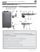
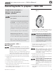
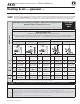

&IGURE Install pipe fittings for relief valve and
pressure/temperature gauge —
$/
./4MOUNTRELIEFVALVEUNTIL!&4%2
HYDROSTATICTESTING
(see legend below)
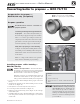
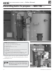
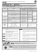
&IGURE Install piping components required for hydrostatic
test (
see legend below)
3
1
Part number 550-142-122/0513
12
TM
GAS-FIRED WATER BOILER — Boiler Manual
1 Boiler supply (outlet) connection, (male, 1” NPT )
2 Boiler return (intlet) connection, (male, 1” NPT )
3 Boiler relief valve, shipped loose with boiler — $/./4MOUNTRELIEFVALVEUNTIL!&4%2HYDROSTATICTESTING.
3a 4%-0/2!2),9/.,9 Insert a ¾” NPT plug in the relief valve tapping of the reducing tee. 4HIS-534"%2%-/6%$AFTER
THETESTANDTHERELIEFVALVEMOUNTEDHERE.
4 Pressure/temperature gauge, shipped loose with boiler
5a Reducing tee, NPT, 1 ” x 1 ” x ¼” on 70/110, & 1 ¼” x 1 ¼” x ¼” on 155, shipped loose with boiler
5b Reducing tee, NPT, 1 ” x 1 ” x ¾” on 70/110, & 1 ¼” x 1 ¼” x ¾” on 155, shipped loose with boiler
6 Nipple, NPT 1” x close on 70/110, & 1 ¼” x close on 155, shipped loose with boiler
7 Reducing bushing, NPT, 1 ¼” x 1”, shipped loose with boiler (155 only)
8 Nipple, NPT 1” x close on 70/110, & 1 ¼” x close on 155, by installer
9 Isolation valve on supply connection, by installer (1” NPT on 70/110, 1¼” NPT on 155)
10 isolation valve on return connection, by installer (1” NPT on 70/110, 1¼” NPT on 155)
11 ¾” NPT boiler drain valve, shipped loose with boiler — after hydrostatic testing, move drain valve to lowest point on the return piping if not
already there.
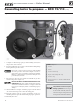
Boiler hydrostatic test (continued)
3
1
(155 only)
(155 only)
11
Piping from system
Piping to system
2