
Install Instructions


CG i
GAS
-
FIRED
wATER
eo1LER
-
sERIEs
a -
Boiler
Manual
13a
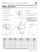
Dimensions
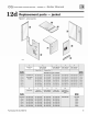
Figure 44 D
im
ensional drawing
(!) Su
pp
ly
piping (n
ote
I)
t
® Return pipi
ng
(note 1)
® Relief valve,
:Y.."
NPT
11\ii
!
@
y,
• NPT to expansion tank/air vent
®
3"
Diameter vent
TOP
VIEYI
ALL
DIMENSIONS
IN
INCHES
·~
,,
..
LEFT
SIDE FRONT
Boiler
Supply
Return
Ga
s
model
tapping tapping
connection
size
number
(inches NPT) (inches NPT)
Note3
(
in
ches NPT)
CGi-25 1% 1 %
Y>
CGi-3 1% 1 %
Y>
CGi-4 1% 1 %
Y>
CGi-5 1% 1 %
Y>
CGi-6 1% 1 %
Y>
CGi-7 1% 1 %
:y..
CGi-8 1% 1 %
:y..
@ G
as
su
pp
ly
piping
®
Dr
ain valve
@J
Gas supp
ly
entrance (
ri
g
ht
or
le
ft side)
® Pressure/te
mp
erature gauge
Hote
l:
804
1
c.r
su
pp
ly
and
re
t
urn
tappings
are
both
1
!.4"
NPT
.
See
T
ab
le 6,
page
20
for
recommended
sys
t
em
wp-
plya
nd
retump!plng
sizes.
Nole
2:
Solle
r
circu
l
ator
is
sh
ipp
OO
loose
.
Circulator
may
be
mounted
on
eilher
boi
l
er
supp
ly or
return
pipi
ng
.
Ci
rculato
r
11ange
provided
witfl
boiler
is
same
si
ze
as
recommend-ed
pi
pe
siZe
in
Tab
le 6,
paoe
20
.
•
19
-'-
...
._..,..,
__
_._
__
,...,.,
RIGHT SI
DE
Gas
uwu
manifold
size
Jackat
Note3
width
(inches NPT) (inches)
'h
10
'h
10
'h
13
'h
16
'h
19
:y..
22
:y..
25
Note
3: Gas piping
from
meter to boiler to
be
si
zed
per local utili
ty
requirements.
68 Part Number 550-142-780/0712