
Install Instructions


CG
i
GAS-FIRED
wATER
BOILER-
sERIEs
a-
Boiler
Manual
llc
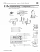
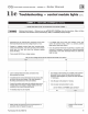
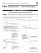
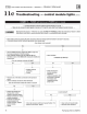
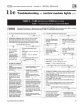
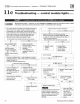
Troubleshooting - control module lights (cont.)
CHART
6 - FLAME
li
ght
fl
ashi
ng
and POWER light on steady
ALSO-
T
ro
ubleshootmg
fa
1
lu
re to establish main flame
I&W
ARNING
I
Electrical shock
hazard-
Wherever you see & TURN OFF
POWER&
, follow the instructions. Failure to follow
instructions
co
uld resuk in severe personal injury, death,
or
substantial property damage.
.
Ale
ma
in manual
shutoff
va
l
ve
and
bo
i
le
r
gas
valve
open?
-·
Is pilot
fl
ame
visible
th
r
ough
inspection
port?
No Yes
r-
No Yes
A
TURN
OFF
POWER&
to
boiler
at
service swi
tch
or
br
eaker
.
• •
.
Open
ma
in
manual
shut
off
valve
and
bo
iler
gas
valve
(
per
.
Check
the
volt
age
ac
r
oss
.
Make
sure
ground
wire
.
Operating
instruct
ions
in this manual). Wail at least 45
seconds
.
t
erm
i
nals
PV
and
C
of
the
terminal is securety fastened
.
Tum on power at servi
ce
switch or breaker. Allow boie-r to cyde .
gas
valve
.
to
cont
rol
modu
le mounting
Is
24
VAC
present
there?
sc
r
ew
.
Does
FLAME
light
flash
now?
Yes
I I
No
l
No
I I
Yes
r-
+
•
.
V
erify
in
let
gas
pr
essu
re
at
gas
.
If
the wiring from
the
.
Check
th
e voltage
ac
r
oss
.
Bo
i
le
r should
be
in
valve:
contr
ol
module
to
gas
terminals
MV
and
C
of
th
e
normal
opera
tin
g
Natural
gas
- s .o· W.C. min/14.0.
vatve
is
intact. replace the
gas
va
tv
e.
sequence.
w.c
.
max
contr
ol
module.
Is
24
VAC
present
there?
.
Observe
opera
tio
n
.
Retest.
-
No
I I
Yes
Propane-
11
.0
"
w.c
. min/14.0"
un
til thermostat is
l
satisfied
and
blow
er
w.c
.
max
has
completed
its
Is
gas
present
at
gas
valve inlet
and
pos
t-purge
cyc
le. within above range?
.
Verify i
nlet
gas
pr
essure
at
gas
valve
:
Yes
I
No
•
l
Natural
gas-
5.0" w
.c
. mi
n1
1
4.cr
w
.c
.
max
.
.t. TURN
OF
F POWER .t.
Propane
- 11 JJ" w
.c
. minf14.o· w.c.
max
to
bo
i
le
r
at
serv
ice
switch
or
/s
gas
present
at
gas
valve inlet
and
within
above
range?
br
eaker
.
.
Contact
gas
supp
li
er
to
corr
ect
-
.
Remove
bu
mer
shield
(see
pressure
or
gas
supply.
No Yes
Figure
40,
itMJ
4,
page 63
~
for
loca
tion).
.
.t. TURN
OFF
POWER .t.
+
to
boie
r
at
seiVice
switch
or
.
.t. TURN OFF
POWER&
to
bo
iler at service switch or brea
ke
r.
.
Verify pilot gas line
is
not
breaker.
.
Check
flame
signal-
Detach
sense
l
ead
from
ign
ition
contro
l
k
il
ked,
obstructed or
.
Remove
burner shield (see
(
Figure
38,
item
8,
poge 53).
damaged and
is
cooectly
Figure
40,
item
4,
page 63 for
.
Connect
negative
l
ead
of
MICROAMME
TER
to
con
trol
sense
attached to pilot and gas
toca
tion
).
t
erm
inal (
Figure
38,
item
B. page
53
).
Connec
t
pos
itive l
ead
of
Vflve.
+
MICROAMMETER
to
sense
wire.
.
Verify
po1ot
ignition electrode,
.
Verify
pi
lo
t burner
is
securely
.
DIS
CO
NNEC
T
red
wire connected to terminaJ
MV
of
t
he
gas
electrode ceramic and spark
attached
to
p
il
ot
brac
ket, bracket
valve.
lead
v.Ye
from control are in
is
secu
rely attached to cr
oss
tie,
.
T
um
on
powe
r to
bo
iler
and
allow to cycle.
As
soon
as
pilot is
good coodtioo.
Spal1<
gap
and
there
is
no
corros
ion
on
the
burni
ng,
the MICROAMMETER should read
at
least 1.0
should
be
approximately 1
18"
.
parts
which
would
affect
the
micr
oamp.
.
C<Xrect
any above problems,
ground
pa
th
for
flame
sense .
Is
flame signaf
at
least
1
.0
microamp?
replacilg pilot W
buner
or
.
Verify
t
ha
t pil
ot
flame rod, flame
No Yes
wi
rilg
is
damaged.
rod
ceramic
and
l
ead
wire
fr
om
•
.
Reinstall burner shield
to
control
module
to
ftame
rod
are
in
operate boiler
for
retest after
good
cond
i
tio
n.
.
If
none
of the
pr
evious st
eps
any changes
or
correctioos.
(including
replacing
pi
lot)
.
If
the
wiring from the
.
Correc
t
any
above
pr
ob
lems •
con
trol
module
to
gas
.
tf
none
of
the
above corrects
r
ep
lacin
g
pi
l
ot
if
burner
or wiring
corrects
problem
.
then
rep
l
ace
va
l
ve
is
intact,
rep
l
ace
the
problem. then replace
the
is
damaged.
t
he
contro
l module, reinstall
contro
l
module
and
re
t
est
control
modu
le and retest.
burner shield
and
re
t
est
Part
Number
550-
1
42-780
/0712
59