
Install Instructions


CG
i
GAS-FIRED
wATER
BOILER-
sERIEs
a-
Boiler
Manual
llc
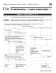
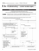
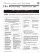
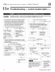
Troubleshooting - control module lights (cont.J
CHART
2-
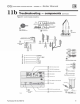
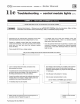
TSTAT CIRC & POWER lights flas
hm
g
-
Usually
indicates
48
VAC
on
thermostat
circuit
(stray
voltage)
-
I&
WARNING
I
Electrical shock hazard - Wherever you
see
.t. TURN OFF
POWER&
, follow the instruction
s.
Failure to follow
instructions could result in severe
personal injury, death, or substantial property damage.
.
Disconnect the two external wires connected to the
bo
iler
.
If a voltage does occur under any condition, check and
thermost
at
leads (two black l
ow
voltage leads in
J-
box). correct the external
wir
ing. (This is a common probl
em
Connect a
vo
ltmeter across these two incoming wires .
when using 3-wire zone valves.)
.
Close each thermostat, zone valve and relay in t
he
external
.
Once the external thermostat c
ir
cu
it wiring is checked and
c
ir
cuit one at a time and check the voltmeter reading correct
ed
if
necessary, reconnect the external thermostat
across the wires. circuit wires to the
bo
iler thermost
at
wires and allow the
There should NEVER
be
a voltage reading .
bo
iler to cycl
e.
.
Did you find a voffage across the
1\Vo
external thermostat circuit wires?
Yes
No
.
Leave external
bo
iler thermost
at
connection wires
.
If no vonage is found under any condition
of
t
he
external
disconnected from
bo
il
er.
th
ermostat c
ir
cuit, connect the two boiler thermost
at
connect
io
n leads toget
he
r
(o
r jumper t
he
bo
iler aquastat
.
Troubleshoot the external thermostat c
ir
cu
it until you find
T-T terminals) .
the source
of
the
st
ray voltage. (
Pa
y close attent
io
n to
the wiring connect
io
ns to 3-wire zone valves.)
~
.
T
um
off
power to the boiler f
or
1 minute.
.
Co
rr
ect the pr
ob
l
em
and repeat the voltmet
er
test above,
T
um
on
power and allow
bo
iler to cycle .
.
verifying t
he
re is no
lo
nger a
vo
ltage reading under
any
condition in the external thermost
at
circuit.
Do the TSTAT and POWER lights sli//tiash?
.
An
isolating relay
may
be
required .
- No
I I
Yes
.
Boiler should now operate
pe
r t
he
normal sequence
of
I:
Repla
ce
control module .
operat
io
n shown in
Figure
30, page 38.
Retes
t.
Part Num
ber
550-142-780/0712 55