
Install Instructions


CG i
GAS
-
FIRED
wATER
BOILER-
sERIEs
3-
Boiler
Manual
11 a Troubleshooting - procedure
!&
WARNIN
G!
Labe
l
al
l wires prior to dis-
connection wh
en
se
rvi
ci
ng
cont
rols.
W
irin
g e
rr
ors
ca
n
cause
im
proper
and
dan
ger-
ous
opera
t
ion.
Check
the
following:
I. Wire connectors to control mod
ul
e are secur
ely
plu
gg
ed
in
at module and
or
ig
inating control.
2.
Air
p
ress
ure
S\vitch
hoses are proper
ly
and securely plugged
in
a
nd
are not
damaged.
!&
WARNING
!
N
eve
r jmnper (byp
as
s) ro
ll
-
out therm
al
fuse eleme
nt
or any other device
excep
t
fo
r
mo
mentary t
es
ting as
outlined in
Tr
oub
leshoot-
Ing
Charts. S
eve
re personal
injury, death
or
substantial
property damage can result.
3.
Gas pressures:
a.
With bo
il
er off-
13
"
w.
c. maximum natural
or
propane g
as
pres-
sure u
ps
tream
of
gas va
lve.
b.
With
bo
il
er on:
s• w.c. minimum natural gas
pr
essure
or
11
"
w.c.
propane
gas
pressure u
ps
tream
of
gas
valve.
3 in" w.c. minimum natural gas
pr
essure
or
10"
w.c.
propane
gas
pressure d
ow
n
st
ream of gas val
ve-
Ca
n be adjusted by regula-
tor on gas valve.
4.
Ve
r
ify
gas
man
i
fol
d
pressure
(d
owns
tr
eam
of
gas
va
l
ve):
Before
troubleshooting:
a.
Na
t
ural
gas:
Manifo
ld
pressure,high
tire
: 3.
50"w
.c.
1. Ha
ve
the fo
ll
owing ite
ms
:
a.
Voltmeter that
can
check
12
0 VAC
and 24 VA
C.
CGi-4
only-
Manif
o
ld
pressure,
l
ow
tire
: 0
90
" w.c.
while
in
low
fire
at
start·up
(60seconds)
b.
P
ropane
gas
:
Manifo
ld
pressure,high
tire
:
IO
.O
"w
.c.
b. Mi
cro
amm
eter
wi
th
a m
in
i
mum
scale
range
of
0-25.
CGi-4
only-
Manif
o
ld
pressure,
l
ow
tire
: 3S
O"
w.c.
while
in
low
fire
at
start·up
(60
seconds)
c.
Continuity checker.
d U-
tu
be manometer.
c.
If n
ecessa
r
y,
adjust
gas
pr
essure
on
the
gas
va
l
ve
as
sh
ow
n
be
l
ow.
After
adjustments
,
refer
to
page
35
to
check
the
flame.
2. Ch
ec
k for 120 VAC (minimum
102
VAC
to maximmn
13
2 VA
C)
to boiler.
3.
Ma
ke
su
re
the
m1
ostat is calling for heat
a
nd
contacts (including appropriate zone
contro
ls
) are closed. Check for 24 VAC
between
th
e
m1
ostat
wi
re nuts and ground.
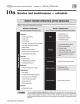
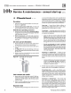
pressure
a4ustment
ll
oueywel two-otage
gas
vtlve
11b
Troubleshooting - components
Air
pressure
switch
NOTICE
NOTICE
50
Make sure boiler
wa
ter temperature
is
I 00
°F
or cooler before starting procedure to obtain
appropriate readings.
The boi
le
r
will
not operate correctly unl
ess
pressure
S\vi
tch hoses are correctly located.
The red hose connects from the right
si
de
(negati
ve)
hose barb to
th
e
flu
e co
ll
ector.
Th
e
w
hi
te hose connects from the left side (posi-
tive)
hose barb
of
the switch to the
co
nnector
box (bet
wee
n
flu
e co
ll
ector a
nd
indu
ce
r)
as
shown in
Figu
re 36, page 49.
Che
ck
pre
ss
ure
s
witch
setting
1. See Figure 36, page
49,
and Table 9.
2.
Remove
both
air
pr
essure
switch
hoses
from
air
pressure
switch.
3.
Install
tees
and
t
ub
i
ng
as
shown
in F
igure
38.
page
49,
to
indined
manometer.
4. Turn off
gas
valve and set thermostat to
call
for
heaL
Inducer
will
r
un
but
burners
will
not i
gn
i
te
.
5. C
he
ck for 24
VAC
between both air pre
ss
u
re
switch terminal
s.
Pa
rt N
um
ber
550
-
142-7
8
0/07
12