
Install Instructions


CG
i
GAS-FIRED
wATER
BOILER-
sERIEs
a-
Boiler
Manual
lOb
48
Service &
maintenance
- annual
start-up
<cont.)
0
Check/test
•••
Gas
piping
1. Sniff n
ear
fl
oor
and
aro
un
d boiler area for
any
in
-
dic
ation
of
a
gas
leak
.
2.
Test
gas
piping
using
bubble
test,
per
Section 5
of
this manual, if there is
an
y indication
of
a leak.
Cold fill
and
operating
pressures
1. While
the
system is cold, n
ote
the
pressure
r
eading
on
th
e
bo
iler pressure/temperature gauge. Verify
th
at
co
ld till pressure
is
correct
2. Watch
the
pressure
as
th
e boiler a
nd
system heat
up
to
ens
ur
e pressure rise
is
normal. Too
hig
h a rise
wo
uld
indicate a wate
rl
ogged
or
un
dersized expan-
sio
n tank.
Air
vents
and
air
elimination
1. In
spect
automatic
air
vents (if used). Also inspect
air
sepa
rat
ors
to
ens
ur
e
they
ar
e
operat
i
onal.
2.
The
cap
must
be unscrewed one
turn
to all
ow
air
to
escape.
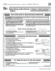
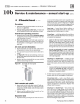
3. See
Figure
34.1f the
air
vent
is
leaking,
re
move cap
A
and
briefly
push
valve B
and
th
en
re
lease to clean
the valve seat.
4. R
ep
la
ce
cap A
by
twi
st
ing all
the
way on
to
valve B
and
then
unscrewi
ng one
turn.
Figure
34
Limit
controls and
cutoffs
1.
In
spect
and
te
st
the boiler limit
co
ntr
ol Verify
op
-
era
ti
on
by
turnin
g
con
tr
ol
set
po
int below
bo
iler
temperatur
e. Boiler sho
uld
cyde
off. Return dial to
original setting.
2. Inspect
and
test
add
itional limit controls
or
l
ow
water cutoffS in
st
all
ed
on system.
Expansion
tank
1. Expan
sio
n tanks provi
de
space for water
to
move in
an
ou
t as the heating system water
exp
an
ds due to
tem
per
a
ture
increase or contracts
as
the water cool
s.
Tanks
may
be
ope
n,
dosed
or
diaphragm or bladder
type.
SeeSection4
of
this
manu
al for suggested best
location
of
expans
ion
tanks
and
air
e
limm
ato
r
s.
Open-type
- located above highest radiator
or
baseboard
mlit
, usually
in
th
e attic
or
closet. Has a
gauge glass
and
overflow pipe
to
a drain.
Closed-type
- welded gas tight
and
located above
boiler. Tank
is
partia
lly tilled wi
th
water, leaving
an
ai
r
cu
sh
ion
for
exp
an
sion.
Mak
e
sur
e tllis type
of
tank
is
fitted wi
th
a
tank
IHtlng, such as
th
e B & G Tank-
Trot
or
Taco
Taco
-
TroL
This
fitting reduces gravity circula-
tion
of
air
-
sa
turated
ta
nk
water
back
to
the
system
and
prevents
the
air
from
bubb
ling
up
thr
ough
th
e water
as
it returns from
the
system.
Do
not
use
automatic
air
vents
In
systems
with
closed-type
tanks.
The
air
will escape
from the
system instead
of
re
turn
ing to the tank.
Even
tua
lly, the
tank
will wate
rl
og
and
no longer
contro
l pressurization.
Th
e boiler relief valve
will weep
frequ
en
tl
y.
Diaphragm
-
or
bladder
-
type
- welded gas tight
wi
th
a
ru
bber
membra
ne to
separ
ate the
tank
pres-
surizing
air
and the
wa
ter. May
be
locat
ed
at
any
po
i
nt
in
the
system, b
ut
m
os
t often fo
und
n
ea
r
th
e
bo
ile
r.
Syste
ms
with this type of expansion
tank
require
at
least one
automatic
air
vent
, prefe
ra
bly
lo
-
cated
on
t
op
of
an
ai
r eli
minat
o
r,
as
shown
in
exan1ples
in
manual
Section 4.
2.
If relief valve has tended to weep frequ
en
tl
y,
th
e
ex
-
pansion
tank
may
be
wa
terlogged or u
nd
ersized.
Closed
-
type
tank
-
tank
is
most
lik
ely
water
-
logged.
In
stall a
tank
fitting
if
not a
lr
eady installed.
The
n
check
fill
level
per
fittin
g
ma
n
ufact
ur
er
's
instructions.
If
till level is correct, check
tank
size
aga
inst m
an
u
facturers
in
structions.
Replace
w
ith
a larger
ta
nk
if
necess
ary
.
Diaphragm
-
or
bladder
-
type
- first, check
tank
size to
be
su
re it is large
eno
ugh for
the
system. If
size is t
oo
small,
add
additional tank(s)
as
neces-
sary
to
provide sufficient expansion . If
tank
size is
large
eno
ugh, remove tank from system
and
check
charge pressure (usually
12 psig for residential
ap
-
plication
s).
lf
tank
won
't
ho
ld pressure, memb
ran
e
has been
dama
ged. Replace tank.
Part
Nu
mber 550-142-780/07
12