
Install Instructions

CG
i
GAS-FIRED
wATER
BOILER-
sERIEs
a-
Boiler
Manual
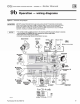
9 b Operation - wiring diagrams (contin
ued
>
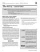
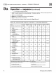
Figure 32 Ladder
wi
rin
g di
ag
r
am
40
lA
WARNlNG
!
Electricol
shock
huard-
can
cause seve
re
in
jury or death.
Di
sconnect
power
befo
re i
ns
taling
or
se
rvici
n
g.
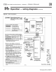
Legend
for ladder wiring diagram
120
VAC
fie
ld
wiring
L
ow
voltage
lie
id
wir
in
g
120
VAC
fadory wiri
ng
Low
voltage
&actory
wiri
ng
H
9l
voltage
spark
ignition
wiri
ng
Ground
coooectors
T1ble
G:
Gl.$
valve termin1b and
anti~ipato
r
tetting:s
Gas
va
lv
e
"A.
·e
"
·c
·
Mll!C
'*«
....
Honeyw
el
VR8204
MVIPV MV PV 0.6
Hoocywc
l
VR8304
MV
IP
V
MV
PV
0.8
White-Rodgers
S6E 2
3
OM
WMo-Aodgo<'$
36C
~
•
3
• T
erm
i
nals
2-4
are factorrj
um
p
er
ed on the
Wh
i
te
-
Rodgers
36C
gM
valve.
1.
All
wiring m
ust
be
in
stal
l
ed
in
acco
rd
ance
with:
0.
7
A.
U.
S
.A.-
N.E.C.
And
any o
th
er
n
at
i
ona
l,
state
,
or
lo-
ca
l
code
requ
i
re
men
ts
.
a.
Cana
da- C.
S.A
.
C22
,1 c.e.c.
Part1
and
any
ot
h
er
na
ti
onal
, p
rovi
n
ci
al,
or
l
oc
al
code
requ
i
re
me
nts
.
2.
Pi
lo
t l
ead
wi
r
es
are
not
f
ie
ld
r
eplacea
bl
e.
Rep
la
ce
pi
lo
t
asse
m
bly
if
necessary
.
3.
11
any
of
th
e or
ig
i
na
l
wi
re
as
s
up
pl
ied
with
the
app
li-
an
ce
m
ust
be
replaced,
u
se
min
im
um
105
•c
wire
or
eq
ui
va
lent,
Excep
tio
n-
wi
res
to
a r
ollou
t T
FE
must
be
200
•c
or
e
qu
iv
alent
4. T
her
m
osta
t
an
ti
ci
pator
setting
(s
i
ng
le
zone
) -
see
T
able
G
fo
r
ant
ici
pa
t
or
setti
ng.
depend
i
ng
on
whic
h
gas
valve
is i
nsta
le
d in
boile
r.
5. F
or
muh
iple zoni
ng
, u
se
e
ith
er z
one
valves
or
ci
rculators
,
Refer
to
the
compo
n
en
t m
anu
f
ac
tu
rer
's I
I>'
stru
cti
ons
and
this
m
anua
l
fo
r
ap
pl
ica
ti
on
and
wi
ring
su
gges
tions.
6.
Refer
to
contro
l
compo
n
ent
i
nstru
ctions
packed
with
tile
boile
r f
or
applicat
i
on
i
nf
or
matio
n.
7, Wi
re
any
add
iti
ona
l limit
co
ntrols (
lo
w
wa
t
er
c
ut
-<JH,
addit
io
nal
high li
mit.
e
tc.)
in
series
with
bo
i
ler
rollout
TFE
and
spil
switc
h
as
sh
own
.
Q
Hot
11
1<-
------
1
20VAC--------<
..
'\
SERV!Cf
SWITCH
Neut
ral
Gnd
i *
HIGH
VOLT
~
~
-~
·
..
LO
~
IGtiTION
ELECTRODE
D
)o
O·R-
<1
.__
__
_,
._
____________
~
t~~;~,
----~
II
24VAC
f-
--------
<J
~Power
THERMOSTAT*
i-
----:1.
a.--~·
~Tsta
t-Ci rc
<;"
:
__!
*
+-
0-HW--
(
if-
u-
se-od)"l
cf
BOILER
SUPPLY
IMI"""
-1
TEMP.
SENSOR
I
<f
'-
-1
ROLLOUT
*
Additiona
l
m l
im
i
ts
(
no
te
7)
~
,..
~L
i
m
h
*
Outd
oor i
""
·"""
-
-1
Tem
pera
tu
re
J
,;
,
Senso
r
(
~
usedll-;....---1
11----
~.-J..~
:
o-
--
-1
~Purge
AIR
PRESSURE
SWITCH
PI
L
OT
F
LAME
SE
NSOR
r--
.J~F
i
ame
.!
HIGH
VO
LTAGE
Control Module
PilOT G
AS
VALVE
A
·c-
\(
"A"
-
·r.
MAIN
v-
GAS
VALVE
S
ee
Tab
le G
Low Voltage Section
P
IL
OT
G
AS
VALVE
-.11.
"PV"
v
"
C"
593748
For
CGi
-4
only
Part
Number
550
-14
2-780/0712