
Install Instructions

CG i
GAS-FIRED
wATER
eotLER-
sERIEs
3-
Boiler
Manual
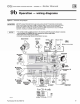
9 b Operation - wiring diagrams
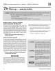
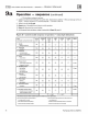
Figure
31
Schematic wtr
ln
g diagram
lA
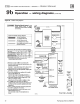
CAUTlON
!
DO NOT connect directly from 3-wlre zone valves
to
the
T-
T terminals
on
the boiler.
When
using
3--..ire
zone
valves.
instal an
isola
~o
n
relay.
Connect the
zone
va
lve
end
switch
wires to
the
Isolation
relay
coil.
Connect
the
Isol
ation
relay
coo
tact
across
the
boiler T-T
termina
l
s.
Failure
to
comp
ly
can
resullln
damage
to
boiler
components
or
cause
un
re
li
ab
le
operation,
resuhlng
In
possib
le
severe
property
damage.
NOTICE
• The
con
trol
modu
le
Is
polarity-sensi
tive
to
the
Incoming
120
VAC
power
. If polarity is
reversed
,
contro
l wil
flash
the
POWER
light
when
powered
and wil not
cycte
boile
r,
• A
ll
contacts
shown
without power
app
l
ied
.
• Connector
and
status l
ig
ht locations/orientations
may
vary.
I
NDUCER
MOTOR
CIRCULATOR
e
Neutr
al
e
Gnd
I
I
FI
ELD
WI
RING
*Item
s not provided
59374b
*OUTDOOR
T
EMPERATURE
SENSOR
(if
used)
Part
Nu
mber 550-142-780/0712
[IIJ
Te
rm
inal
bloct
(See
ToableGt
For
CGi
-4 only
*
39