
Install Instructions

CG
i
GAS-FIRED
wATER
BOILER-
sERIEs
a-
Boiler
Manual
9
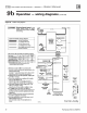
Department
of
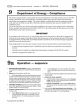
Energy - Compliance
This boiler
is
equipped with a control system that automatically adjusts a time delay period to
tu
rn
on
the boiler
during a call for heat. This
is
accomplished by circulating available
hot
water in the syst
em
while measuring
water boiler water temperature changes. The control calculates a suitable delay based
on
temperature measure-
ments
and
turns the boiler
on on
ly after it determines that the demand for heat cannot
be
satisfied with the
available
hot
wat
er.
Due to the wide variety
of
controls used in boiler installations, this control
is
also equipped with
an
adjustment
for
the
calculated time delay period (ECONOMY ADJUST). In
the
MIN position, the time delay
is
zero
and
the
IMPORThNT notice below must
be
observed:
IMPORTANT
In
accordance with Section 325 (f) (3)
of
the Energy
Po
licy
and
Conservation Act, this boiler
is
equipped with
a
fea
tu
re
that saves energy by reducing the boiler water temperature as the heating l
oad
decreases. This feature
is
equipped with an override which is provided primarily to permit the use
of
an e.nernal energy management
system t
hat
serves the same function.
T
HI
S
OVE
RR
IDE
MUS
T
NO
T BE USED UNLESS
AT
LE
AST
ONE
O F
TH
E FOLL
OW
I
NG
COND
ITI
ONS
IS TRUE:
An
external energy management
system
is
installed that
reduces
the
boiler
water
temperature as the h
eat
i
ng
load
decreases.
Tilis bo
il
er
is
part of a m
od
ul
ar
or
mul
tip
le
bo
il
er
syste
m h
avi
ng a total input
of
300,000
BT
U/hr
or
g
rea
t
er.
This bo
il
er is equipped with a
tan
kl
ess
coil.
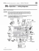
9a
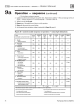
Operation - sequence
I . Read Operating instructions
on
page
41. This in
fom
1
atio
n
is
also
located on a
labe
l on
the
i
ns
i
de
of
the
boiler
jacket
door
pane
l.
b.
If pilot
does
light
and
co
ntrol mod
ul
e
se
n
ses
fla
me
current,
spark
generator
is
turned
off and m
ain
valve
opens.
2.
Raise room them10stat
to
call
for
heat.
a.
While
attempting
to
satisfy
the
heat
dema
n
d,
th
e control
module monitors
the
boile
r
te
mperature
changes
via
the
tem
-
perature sensor and determi
nes
whether or not
th
e
ava
i
lab
le
hot
water
will
satisfy
th
e demand, only running
the
circulator.
If additional heat
is
needed,
th
e
seque
n
ce
co
n
tinues.
Whe
n
DHW (if u
sed)
ca
ll
s f
or
h
ea
t,
sequen
ce
above
is
bypasse
d.
3. Circulator energizes. Iflimit circuit
is
closed,
the
inducer
sta
rt
s.
After
p
ress
ure
swi
t
ch
proves
proper
ai
rfl
ow,
control
modu
le
initiates I 0-second prep
urge.
4.
Control module sparks
the
pilot and opens pilot
valve
in
m
ain
gas
valve.
a. If pilot
does
not
light within
IS
seconds,
pilot
valve
is
closed
and spark generator is turned
off.
Control
module initiates a
IS
-
seco
nd postpur
ge,
th
en
starts a
new
cycle.
Pa
rt
Nu
mber 550-1
42-7
80/0712
s.
The
CGi
-4 timer
relay
de
l
ays
h
ig
h
fir
e
for
th
e
first
60
seco
nds
of
main
fl
am
e.
6.
During main burner operation:
a Control m
od
ul
e monitors p
il
ot
fl
ame cur
re
n
t.
If signal
is lost,
main
valve
doses,
spa
rk generator
activates
and
sequence returns
to
step 4.
b.
If power
is
intenupted, control
syste
m shuts off pilot
and m
ain
gas
valves
and restarts at
step
1
when
powe
r
is
r
estored.
7.
In
th
e
eve
nt
the
limit control shuts down
the
boiler - The
co
n
trol
module
doses
the
pilot and
main
gas
valves,
but
keeps
the
inducer operating
for
IS
-
seco
nd postpur
ge.
37