
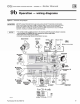
Install Instructions

CG i
GAS
-
FIRED
wATER
BOILER-
sERIEs
a-
Boiler
Manual
6
Field
wiring
I&
WARNING
!
NOTICE
Fo
r
yo
ur s
af
ety,
tum
off electrical power supply
at
se
rvice
entrance
panel before making any
electrical
connections
to avoid possible electric
shock h
aza
r
d.
Fai
lure to do so can cause severe
person
al
inju
ry
or death.
Wiring
must
be
N.
E.C.
Cl
ass
1.
If ori
gi
nal rollout thermal fuse element
wi
re
as
supplied
wi
th boi
le
r must be replaced, use on
ly
type
200'C
wi
re
or
equivalent. If other origin
al
wi
ring as
su
pplied with
bo
il
er must be rep
la
ced,
type
105'C
w
ir
e
or
eq
ui
va
lent must
be
used.
Boiler must
be
electrically ground
ed
as required
by National Electrical Code ANSI/NFPA 70 -
latest edition.
Electrical
installation
must
comply
with:
1. National
El
ectrical
O>
de and
an
y other national, state, pro-
vi
n
cial
or local
co
des or regulation
s.
2. In Canada,
CS
A
C2
2.1
can
adian Electrical Code Part
1,
and
any local codes.
Wiring
connections
Boiler
is
shipped w
ith
controls completely w
ir
ed
Thermostat
1. Connect thermostat as shown on wiring
di
ag
ram on bo
il
er.
2. Install on inside wall away from influences of drafts,
hot
or
cold
water
pipes, lighting fixtures, television. sun rays,
or
fireplaces.
3.
If thermostat has a heat anticipator, set heat anticipator
in
thermostat to mat
ch
power requirements
of
equipment con-
nected to it. 1f
co
nn
ec
t
ed
d
ir
ec
tl
y to bo
il
er, set for
0.1
amps
plus gas valve c
urr
e
nt
. S
ee
inf
om1ation
on
wiring diagram
as shown
in
Fi
gure 32, p
age
39.
Fo
r other d
ev
ices, refer to
manufacturer's specifications. Wiring diagram on boiler
give
s
setting for control m
od
ul
e
and
gas val
ve.
Al
so
see
in
struc
ti
ons
with the
m1
ostat.
DHW
1.
O>
nn
ect
DHW
aquastat as shown
in
wiring bel
ow.
Economy
ftmction isn't utilized with
DHW
input.
Junction
Box
(furnished)
1.
O>
nn
ect
12
0 VAC
po
we
r wiring as
sh
own
in
Figure 27.
2.
Fused disco
nn
ect
or
service swit
ch
{15 amp. recommended)
may be mounted on this b
ox.
For those installations with
local codes
wh
ich prohibit
in
sta
ll
a
ti
on
of
fused disconn
ec
t
or
serv
ic
e swit
ch
on boiler,
in
sta
ll
a 2 x 4
cove
r p
la
te on the
bo
iler junction box and mount
th
e service switch
re
motely
as required by the code.
Wiring
multiple
zones
Refer to zone
valve
manufacturer's
li
terature
fo
r
wi
ring and
ap
-
pl
ication. A separate
t
rans
f
o
m
~e
r
is requir
ed
to power
zo
ne va
lves
.
Zoning with circulators requires a relay for each circttlator.
IACAUTIDN
I
DO
NOT
connect
directly from 3-wire
zone
valve.s
to
the
T-T
terminals
on
the
boiler
.
Wh
en using 3·wire zone val
ves,
install an isolation
r
elay.
Co
nn
ect the
zo
ne val
ve
end switch
\vi
res to
the isolat
io
n re
la
y coi
l.
Co
nn
ect the isolation
re
l
ay
contact across the boiler T-T term
in
als.
Failure to
comply can result
in
damage to boiler components
or cause
un
reliable operation, resulting in severe
property damage.
NOTICE
The CGi co
ntr
ol module
is
polarity-sensitive.
Th
e hot and neutral wires must
be
c
OJm
ected to the correct leads.
A flashing POWER light usually indicates reversed polarity
of
12
0
VA
C lead wires.
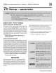
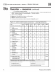
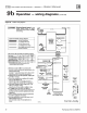
Figure 27
Fi
eld
w1r1ng
co
nn
ec
-
tions -
se
rv
ice switch,
DHW
(
If
used) and
thennostat
(or end
sw
itch)
pr
ov
id
ed
by
In
st
al
l
er
t
120V
AC
A
Hoc
"TT'
N
eu
tral
I I
II
1 I U
f
...
s. ..... ,
~
~
'""""
:r
I
....
..-.
u
~
I I
~
I
Part Number 550-142-780/0712
;>
i
I
~;'
;:;.
~
"'
I
1
.......
~
1
I I
I I
I I
I I
) )
" "
"'
"
-·-
;>i
I
Ot<
W I
I
'
~"..:'
I
I I
I I
I I
I I
) )
" "
...
S!t
Yioe
sw~
h
.,.._
Th
ermost
at
or
end
swi
ch
·--
31