
Install Instructions


CG i
GAS-FIRED
wATER
BOILER-
sERIEs
a-
Boiler
Manual
5
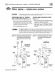
Gas
piping
Connecting
gas
supply
piping
to
boiler
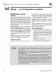
I. Remove jacket front panel
and
refer to Figure
26
to
pipe gas
to
boiler.
a.
In
sta
ll drip leg
at
inlet
of
gas connection
to
boiler.
Where local utility
r
e<Jui
res drip leg
to
be extended to
th
e fl
oo
r, use appropnate length
of
pipe between cap
and
tee.
b.
In
sta
ll
ground
joint union for servicing, when re-
quired.
c.
In
sta
ll
manual
shutoff
valve
in
gas s
upp
ly pipi
ng
out
-
side boiler jacket when required by local codes or utili
ty
requireme
nt
s.
d.
In
Canada
- When using manual
ma
in shutoff valve, it
must
be
identified
by
the installer.
2.
S
up
port
piping wi
th
hangers,
not
by
boiler or its accessories.
3.
Purge
all air from gas
supp
ly pipin
g.
4. Before placing boiler
in
operation, check boiler
and
its
gas
connection
for l
eaks
.
a.
Close
manual
main
shutoff
valve during any press
ure
testing at less
than
13" w.c.
b. Disconnect boiler
and
gas
valve from
gas
s
up
ply
piping during any pressure testing greater
than
13" w.c.
'"
1
&-,-,
W
.,.,.,
AR
,.,.
N
""
IN
~G
I
Do
not
check
for
gas
leaks
with
an
open
flame -
use
bubb
le
test
Fa
ilure
to
use bubble
test
or
check for gas leaks can cause severe
personal inj
ur
y,
dea
th
or
substantial property
dan
1a
ge.
5.
Use
pipe
dope
compatib
le
with
propane
gases.
Apply
sparingly
on
ly
to
male
th
reads
of
pipe
joints so
that
pipe
dope
does not bl
oc
k gas
fl
ow.
I&
WARNING
!
Failure
to
app
ly
pipe
dope
as
detailed above
can result in severe personal injury, death
or
Natural
Gas:
I. Refer
to
Table 7 for pipe length
and
diameter. Base
on
rat
ed
bo
il
er
inp
ut
{divide by
1,
000
to
obtain cubic feet per h
our).
Table 7 is only for gas with specific
gravity
0.60,
with
a
pressure
drop
through
the
gas
piping
of
0.30" w.c. For
additional
gas
pipe sizing infom1ation, refer to ANSI Z223.1
(o
r B
I4
9.I
or
BI49.2 for Cana
dian
installations).
2.
Inlet pressure required
at
gas val
ve
inlet:
tvtaxim
um: 13"
w.c.
tvtinirn
um: 5"
w.c.
JV!anifo
ld gas pressure: 3.5" w.c.
3. Install 100% l
oc
kup gas pressure regulator
in
su
pp
ly line if
inlet
pressure
exceeds
13" w.c. Adjust for I 3" w.c. maxi-
mum.
Propane
Gas:
I.
Co
ntact
gas
s
up
pli
er
to size pipes, tanks
and
I
00%
l
oc
kup
gas press
ure
regul
ato
r.
2.
Adjust propane
supp
ly regulator provided
by
gas
supp
lier for
13"
w.c.
maximmn
press
u
re.
3. Inlet pressure required
at
gas val
ve
inlet:
Maxim
um
: 1
3"
w.c.
tvtinirn
um:
11
,
w.c.
Manifold gas
pr
ess
ur
e: 10" w.c.
substantial property damage.
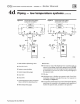
Figure
26
Gas
su
pply pip
in
g
Table 7 Pipe capacity for
0.
60
specific
grav~y
natural
gas
Gas
pipe
Capacity
of
pipe
for
pipe
size
of:
length
(Capacity
in
cubic
feet
gas
per
hour)
(fee
t)
1/a
"
~·
1"
1f/•"
1
1/a"
10
132
278
520
1050 1800
20
92
190
350 730
1100
30
73
152
285 590 880
40
83
130
245
500 760
50
58
115
215
440
670
75
45
93
175
360 545
100
38
79
150
305
460
150
31 64
120
250
360
71028
30
Part
Number
550
-
142-780/07
12