
Install Instructions


CG i
GAS-FIRED
wATER
BOILER-
sERIEs
a-
Boiler
Manual
4d
Piping
-
low
temperature
systems
<conl
inued
)
From system
8
To
system
Aft~~~~
t:lrcu/4tor
locstlon
II
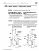
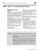
Figure
24
System-bypass piping - Zoning with
zone val
ve
or circulators, return water
130"F or higher - (Aitematlve
to
boiler-
bypass piping
Fi
gures 22 and 23)
3 System
or
zone circulator
7 System temperature valves (see instructions to
the
left for
ad
justing valves)
8 Blend te
mperatur
e gauge
9 Relief valve
10
Automatic air vent (with
diaphra~m
-
type
expan-
sion tank),
or
connect to
tank
fittmg (closed-type
expansion tank).
DO
NOT
use an aut
om
atic air vent
when using
dosed
-type expansion tank.
It
wou
ld
allow air
to
leave the system, causing waterlogging
of
th
e expansi
on
tank.
11
Fill valve
12
Diaphragm-type
or
bladder-type expansion tank,
if
used (For d osed-
type
expan
sio
n tank, pipe from
top
of
air separator to
tank
fitting as
in
Rgure
17,
page 21.)
4e
Water
piping-
refrigeration
system
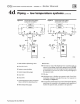
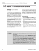
Figure 25 Piping refrigeration systems
System
:I
I
Expansion tank
supply
I
-
- -T•
t
Sh
ut
-
off
Circu
lator
(-<
valve
Water
ch
iller
t
; Strainer
C
he
ek
Bo
iler
B:l
•
valve
II
Sys
tem
t
return
-
-
Ba
lancing
) 1
(1»
va
l
ve
Part Number 550-142-780/0712
Prevent
chilled
water
from
entering
boiler
In
st
all boiler
so
that
chilled
medium
is piped
in
parallel
w
it
h the heating
bo
il
er. Use a
pp
r
op
riate valves to prevent
chilled
medimn
from entering boiler. See Figure
18
for
typical installation
of
balancing va
lve
and
check valve.
If boiler is
co
nn
ec
ted
to
heating
co
ils located in air han-
dling
units
where they can be exposed
to
refrige
rat
ed
air, u
se
flow
co
ntr
ol
va
lves
or
o
ther
aut
omatic means
to
prevent gravi
ty
circulati
on
dur
ing cooling cycle.
29