
Install Instructions


CG
i
GAS-FIRED
wATER
BOILER-
sERIEs
a-
Boiler
Manual
4d
Piping - low
temperature
systems
<conl
inued)
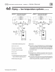
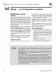
Figure
22
Boiler-bypass p
ip
ing - Zoning with
circulators - (Aitematlve
to
primary/
secondary piping
Fi
gures
20
and 21)
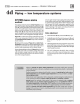
Figure
23
Boiler-bypass piping - Zoning wllh
zone valves - (Alternative to primary/
secondary p
ip
ing
Fi
gures
20
and 2
1)
Cold
wat
er
••
Effi
I I
1
Boiler isolation (balancing) valves
2 Flow/check
va
l
ve
3 System or zone circulator
4 System temperature gauges
5
Zone
va
l
ve
6
Drain
va
l
ve
7
System temperature valves (see
in
-
str
uctions
to
the left for adjusting
valves)
8 Blend temperature gauge
r--------------f-zoN"e-2~---------+
,
.
!
~-----------J
!
' ZONE1 '
f*
1 1 *•
i 5
~
T
-1
:
it.....!
~
---
--
+1
·
6
Cold
-M
~
,.
I
I!!!
710
24
71
025
9 Relief valve
10
Automatic
ai
r vent (with diaphragm-type expansion tank),
or
connect to tank fitting (closed-type expansion tank).
DO
NOT
use
an automatic air vent when using closed-type expansion tank. It
would all
ow
air to leave
the
system, causing waterlogging
of
the
expansion
tank.
11
Fill
valve
12
Diaphragm-type
or
bladder-type expansion tank,
if
used (For
d osed-type expansion tank, pi
pe
from top
of
air
sep
arator to
tank fitting as
in
Figure
17.
page 21).
13
Air separator
and
automatic vent,
if
used (Note that the
fill
va
l
ve
must alwa
ys
be connected to the expan
sio
n tank, regardless
of
location
of
expansion tank, circulator
or
air separator.)
Part Number 550-142-780/0712 27