
Install Instructions
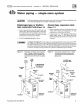


CG i
GAS-FIRED
wATER
BOILER-
sERIEs
a-
Boiler
Manual
4d
26
Piping
-
low
temperature
systems
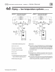
BOILER-bypass
piping
method
Th
is piping method (Figure 22
or
23) is called a boiler-
bypass
be
ca
use part
of
the circulat
or
flow is bypassed
around
the
boiler (through val
ve
7a
).
This
m
ethod
reduces
th
e
fl
ow ra
te
thro
ugh
o
ut
the boiler,
in
order to
raise the average water temperature in the boiler en
oug
h
to prevent flue
gas
condensation. Boiler-bypass piping
is effective for some boilers - including the
CGi -
pro
vided the
fl
ow
rat
es are adjusted according to the
instructions following.
Figures 22
and
23 are alternative piping suggestions
for converted gravity (large water content
or
steam
systems)
or
radiant
heating
system
- for use when
primary/secondary piping
can't
be
applied
(Figure 24
is another alternative, using system bypass in place
of
boiler-bypass piping. Figure 24 however,
is
not
suitable
for radiant heating
app
lications because it does n
ot
protect
the
radiant system
fro
m possible high water
temperature.)
Boiler
-b
ypass piping
ke
e
ps
system
fl
ow rate as high as
possible and temperature drop as low as possib
le,
help-
ing to equalize the building heat distribution.
Temperature
gauges
Gau
ge
4a
is optional if the bypass valves w
ill
be
ad
-
justed using cold
(o
r room temperature) return water
to the boiler. (When setting the valves without gauge
4a
installed - using cold or room temperature water
- assmne the
re
turn
wa
t
er
temperature to
be
6Q•F.
Set
the valves
so
gauge 8 reads at least t
20"F.
Gauge 4b is optional on converted gravity systems,
but
required on radiant heating systems - to display
the water tempera
tur
e being supplied
to
the radiant
tubin
g.
Gau
ge
8 is required on all systems
to
assure reliable
adjustm
ent
of
the bypass
valves.
The
bo
il
er
-mounted
temperature/pressure
gauge can
be
used
if a separate
temperature
gauge
is
n
ot
installed
Valve
adjustment
t. Start with val
ve
7a fully
dosed
and
7b
fully open.
2. Gradually
open
val
ve
7a
while
dosing
valve
7b
until the temperature
at
gau
ge
8 reads 60
°F
higher
than gauge
48
. A minimum 60°F temperature rise
through the boiler assures a low eno
ugh
fl
ow rate
and
high
eno
ugh average temperature to prevent
condensation even with low system
return water
temperature.
3.
Valve
7a
regulates
th
e system
fl
ow rate, wllile valve
7b
regulates
th
e boiler
fl
ow rate.
4.
The
boiler-mounted tempera
tur
e/pressure gauge
may
be
used in place
of
a separate gau
ge
8.
I&
WARNING
!
Failure to
prevent
low
return
water
temperature
to
the
boiler could cause corrosion
of
the
boiler sections or burners, resulting in severe personal injury, death or substantial
property damage.
Radiant heating system piping should include a means
of
r
egulating
the
boiler r
eturn
water
temperature
and
the
system
supply
temperature
(s
uch
as
provided
by
an InJec-
tion pumping
cont
rol
).
Boiler return water temperature will be adequately co
ntr
olled using
th
e methods shovm
in this manual provi
ded
the
system
supply
temperature
is relatively
cons
tent.
DO NOT apply the methods
of
this manual if the
sys
tem is equipped with
an
outdoor
r
eset
cont
rol
. Inste
ad
, provtde controls
and
piping which
can
r
egulate
the
boiler
re-
turn
water
temperature
at
no
less
than
130
°F
regardless
of
sys
tem supply temperature.
Contact your
We
il-Mcl.ain representat
ive
for suggested piping
and
control methods.
Failure to
prevent
cold r
eturn
water
temperature
to
the
bo
il
er
co
uld cause corrosion
damage to
the
sections or burners, resulting in possible severe personal injury, death or
substantial
pr
operty damage.
Part Number 550-142-780/0712