
Install Instructions


CG
i
GAS-FIRED
wATER
BOILER-
sERIEs
a-
Boiler
Manual
4d
Piping - low
temperature
systems <
conlinued
)
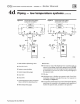
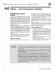
Figure
20 Primary/secondary piping
Z
on
i
ng
wt
th circulators
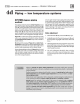
Figure
21
Pri
mary/seconda
ry
piping
Zoning
w1t
h
zo
ne valves
..-
----------f-zo"Ne2--'---------
..
----·,
1
'"---------~
1
I I
:
ZONE1
:
~
~
I
~
' 4
::r::
I 8 ) I
0 (,.1
~
-
~
-
-
--
10
1 Boil
er
isolation (bala
ncin
g)
va
l
ve
s
2 Flow/ check valve
3 System or zone c
ir
culator
4 System te
mp
erature gauges
5 Zone val
ve
8
Dr
a
in
val
ve
7 System temper
atur
e
va
l
ve
s (see ins
tru
c-
tions to the left for adjusting valves}
8
Bl
e
nd
te
mp
era
tur
e gauge
71023
710
22
9 Relief valve
10
Au
toma
tic air
ve
nt {wi
th
di
aphragm-type expansion tank),
or
co
nn
e
ct
to
tank
fitting (
cl
ose
d-typ
e expansion
tank
).
DO
NOT
use an automatic air vent when using d osed-type expansion tank.
It
would
allow a
ir
to
leave the system, causi
ng
waterlogging
of
the
expan
sion
tan
k.
11 Fill valve
12
Di
ap
hr
a
gm-t
ype or bladder-
ty
pe expansion
tank
, if used (For
dosed
-type expansion tank, pipe from t
op
of
a
ir
separator to
tank
fitting as
in
Figure 17
.}
13
Air separator
and
a
ut
omatic
ve
nt
, if
us
ed (Note
th
at
th
e fill valve
must
always
be
connected
to
the expansi
on
tank
, regardless
of
locat
ion
of
exp
an
sion tank, circulator or a
ir
separator.)
Part
Nu
mber 550-142-780/0712 25