
Install Instructions
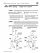


CG i
GAS-FIRED
wATER
BOILER-
sERIEs
a-
Boiler
Manual
4c
Water
piping - multiple
zones
(continued)
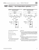
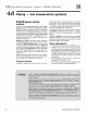
Figure 18 Z
on
i
ng
with circulators Figure
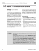
19
Zoning with
zone
va
l
ves
- return
wa
ter 130•F or hi
gher.
-
return
water 130•F or
hi
gh
er.
r----------,
.r--------------1
ZONE
2
~--------+:,
.
i
----;~~~--1
. i
ft
1 1
~
~
! l
I
5
'fD
+
~
·
+---
--
!-'
6
10
Cold
Co
ld
wate
r
wttt
er
fil
l
f
il
~
Ei:l
II
II
71020
71
021
1 Boiler isolation (balancing) valves
10
Automatic air vent (with diaphragm-
type
expansion tank),
or
con-
nect
to
tank
fitting (closed-type expansion tank). DO NOT use
an
aut
omatic air vent when usi
ng
closed-type expansion
tank
It
wo
u
ld
allow air
to
leave
the
system, causi
ng
waterlogging
of
the expansion
tank.
2 Flow/check valve
3 System
or
zo
ne circulator
11 Fill valve
5 Zone valve
6
Drain
valve
9
Re
lief valve
I&
WARNING
l
12
Diaphragm-type
or
bladder-type
ex
p
ansio
n tank,
if
us
ed
(For
dosed
-type expansion tank, pi
pe
from top
of
air sep
arat
or
to
tank
fitting as
Ill
Figure 17.)
13
Air
separator
and
a
ut
omatic ve
nt
,
if
us
ed
(Note
th
at
th
e
fill
valve
must
always
be
co
nnected
to
the
expansion tank, regardless
of
loca-
tion
of
expansion
tank
circu1ator
or
air
sep
arat
o
r.
For systems with possible low
return
-water temperature (such
as
converted gravi
ty
syste
ms,
radiant heating systems a
nd
heat
pu
mp
systems), refer
to
the special piping suggestions
of
Figures
20
-
24
,
as
applies. Failure
to
prevent sustain
ed
low
return
water temper
ature
to
the boiler
co
u
ld
ca
use corrosion
of
the
boiler sections, resulting in severe personal injury,
death
or
substantial property damage.
Part
Nu
mber 550-142-780/0712
23