
Install Instructions


CG i
GAS-FIRED
wATER
BOILER-
sERIEs
a-
Boiler
Manual
4c
22
Water
piping - multiple
zones
Piping
multiple
zones
Follow instructi
ons
on
pages 20
and
21
to
install near-
boiler
or
single-
zo
ne piping. (Also refer to Piping for
radiant
heating
systems
or
converted gravity
sys-
tem
s,
below, if applicable.)
See
Figure 18
or
Figure 19 to co
mp
le
te
in
st
allation.
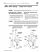
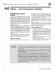
Zoning
with
circulators
(Figure
18)
(return
temp
over
130
•F)
1.
Size each circulator to individual circ
uit
require-
ments.
2. Do not install circulator
on
boiler (except for
pr
imary/secondary piping).
3.
In
stall isolation (balancing)
va
lves to
ad
just
fl
ow
to distribute heat to
all
zones.
Piping
for
radiant
heating
systems
or
converted
gravity
systems
Converted
gravity
(or
steam)
systems
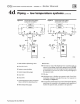
Whenever possible, use the primary/secon
dary
piping
shown in Figur
es
20 or
21
on
page 25. This piping
de
-
sign
al
lows changing boil
er
fl
ow
rate wi
th
o
ut
affecting
primary circ
uit
fl
ow
rate.
If Figures
20 or 21 ca
nn
ot
be
used, use the boiler-by-
pass piping shown in Figure 22
or
Figure 23 on page 27.
You
can also use the piping s
hown
in
Figure 24 on
page
29
(syste
m-b
ypass),
if
th
e redu
ced
flow
rat
e
in
the
heating system will n
ot
cause h
eat
distribution
problem
s.
4. Install
and
w
ir
e a separate relay for each zone
circulator. I&
WARNING
!
Failure
to
preve
nt low
return
water
temperature
to
the
boiler
c.o
uld
cause corrosion
of
the
boiler sec-
tions
or
burner
s,
resulti
ng
in
seve
re
personal injury, death
or
substantial
property damage.
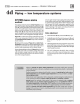
Zoning
with
zone
valves
(Figure
19)
(return
temp
over
130
•F)
t.
In
stall isolation (balancing)
va
lves to
ad
just
fl
ow
to
distribute heat to all zon
es.
2.
Pr
ovide a separate 24-volt
transf
om1er to power the
zone valves.
Size the transf
or
m
er
to handle the total
rated l
oa
d
of
all connected zone valves.
Radiant
heating
systems
Preferabl
y,
use primary/second
ary
piping,
as
shown
in
Figures 20 or
21
on
page 25. Alternativel
y,
use the
method
of
either Figure 22
or
Figure 23 on page 27.
Do
not
use
the
piping of Figure 24 (system-bypass),
because this
method
does n
ot
control radiant system
supply temperature.
lA
CAUTlON
I
DO
NOT
connect
directly
from
3-wire
zone
valves
to
the
T-
T termi-
nals
on
the
boiler
. When u
si
ng 3-wire
zone
va
l
ves,
install
an
isolation
relay.
Co
nnect
the
zone
va1ve
end sw
itch
wires
to the isolation relay coi
l.
Con
nect the
isolation relay contact across the boiler
T-T terminals.
Fail
ur
e to comply can
result in damage to boiler components
or
cause unreliable operation, resulting
in severe property damage.
If radiant system tubing has
no
oxygen barrier, a
heat
e
xchanger
must be used.
I&
WARNING!
Radiant heating system piping should include a means
of
regulating the boiler return water
temperature
and
the system supply temperature
{s
uch as provid
ed
by an injection
pump
ing
control). Boiler return water tempera
tur
e will
be
adeq
uat
e
ly
controlled using
the
methods
shown in this manual provided the system supply te
mp
erature is re
la
tively constanL
DO
NOT a
pp
ly
the
meth
ods
in this manual
if
the system is equipped with an
outdoor
r
eset
control. Instead, provide controls
and
piping which can regulate
the
boiler return water
temperature
at
no less than 130°F regardless
of
syst
em
supply temperature. Contact your
Weii
-McLa
in
representat
ive
for suggested piping
and
control methods. Failure to prevent
cold r
et
urn water te
mp
er
atur
e to
the
bo
il
er
could cause corrosion damage to
the
secti
ons
or burners, r
es
ulting
in
possible severe personal injury, death
or
substantial property dan1age.
Part Number 550-
142-780/07
12