
Install Instructions


CG
i
GAS-FIRED
wATER
BOILER-
sERIEs
a-
Boiler
Manual
4a
Water piping - general information
General
piping
information
If
installation is to
co
mply wi
th
ASME or Cana
di
an r
eq
uireme
nt
s, an
ad
-
ditional high
temperat
ure limit
is
needed
Install control in su
pp
ly pipi
ng
between boil
er
and isolation
va
l
ve.
Set second
co
ntr
ol to mini
nuu
n 20•F
above se
tp
o
int
of
first
co
n
tro
l.
Maxi
mm
n allowable
se
tpoi
nt
is
240•
F.
See
Section
9b
for wiring.
A l
ow
wate
r cu
to
ff
device is required when boiler
is
installed above ra-
diati
on
level
or
by
certain state
or
local codes
or
ins
ur
an
ce
companies. Use
low water cutoff designed for water installations. Electrode
probe
-type is
recommended.
Purchase and install in tee
in
supply piping above boiler.
Use backflow c
he
ck valve in cold water supply
as
required
by
local codes.
Pressure/temperature
gauge
Install pressure/temperature gauge in tee
on
supp
ly piping (as shown in
drawing on page 3).
Isolation
valves
Isolati
on
va
lves are requir
ed
to
enable servicing
of
the boiler's temperature
sensor. Install as shown
in
appropriate piping diagram.
Relief
valve
Install relief valve vertically in W' tapp
in
g on side of
bo
iler. See Figure 16
or
17, page 21,
and
th
e tag attach
ed
to
the
relief valve for manufacturer's
instruct
i
ons.
I&
WARNIN
G!
To avoid water damage
or
scalding due
to
relief valve
. . operation:
20
Discharge line
must
be
c01
mected to relief valve outlet
and
run
to
a
safe
pla
ce
of
dispo
sal.
Te
rmi
nat
e
the
discharge
li
ne
to
eliminate
possibility
of
severe burns should
the
valve disch
ar
ge.
Discharge line
mu
st be as sho
rt
as possible
and
be
th
e s
ame
size
as
the
valve
dis
c
ha
r
ge
c
onnection
throughout its entire length.
Discharge line
must
pitch
downward
from
th
e valve a
nd
ter
mina
te
at least 6" a
bo
ve
th
e
fl
oo
r
dr
ain where any discharge will be clearly
visibl
e.
Th
e discharge line shall
tennlnate
plain,
not
threaded
, with a
ma
te-
rial serviceable for temperatures
of
375°F or greater.
Do
not
pipe
the
discharge
to
any
place
whe
re freezing
could
occu
r.
No
shutoff
valve sha
ll
be
installed between the reli
ef
valve a
nd
boiler,
or
in
th
e discharge lin
e.
Do not plug or
pl
ace any obstruction
in
th
e
discharge
li
ne.
Failure
to
comply with the above guidelines could result in
fa
ilure
of
th
e reli
ef
valve
to
operate, resulting in possibili
ty
of
severe personal
injury,
death or substantial property damage.
Test
the
operation
of
the
valve after filling
and
pr
essur
izi
ng
sy
stem
by
lifting
th
e lever. Make sure
the
val
ve
discharges freel
y.
If the valve
fails
to
operate correctly, replace it with a new re
li
ef
valve.
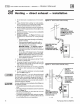
Circulator
The
circulator is shipped loose (wiring pre-attached
to
boiler)
to
allow you
to
locate
it
ei
ther
in
th
e re
turn
or
s
up
ply piping, as desired. See page 3 for a typical instal-
lation.
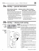
Pipe the expansion tank
to
the suction side
of
the
circulator whenever possible. Install an air separator in
the supply piping. Connect the expansion tank
to
the air
separator
on
ly if the separator is
on
the suction side
of
th
e
ci
rc
ul
ator. Always
in
stall
th
e system
fill
cOJ
mection
at
the
san1e point as
the
expa
nsion
tan
k
co
nnection
to
the system. Figures 16 and 17 show typical
near
-boiler
pipi
ng
connections.
System
water
piping
See Figure 16 (diaphragm-type
or
bladder-type expan-
sio
n tank)
or
Figure 17 (closed-type expansion tank)
and
Table 6, for near-boiler
and
single-zone systems
desi
gned
for return water at least
1300F.
See pages 22-
23
to
co
mplete multi
pl
e-zone pipi
ng
or
pages
24
-29
to
co
mpl
ete
pipi
ng
for
rad
iant heating
systems
or
converted gravi
ty
systems (large-volume
systems originally
designed for circulation
by
na
tu
ral
co
nvection rather
than
a pump). See page
29
for boilers
used wi
th
refrigeration systems.
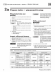
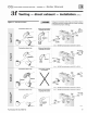
Table 6 Water pi
pe
size
(based
on 20•F ri
se)
Boiler
To
F
rom
model number system system
CGi-25
'14" '14"
CGi-3, 4, 5 1" 1"
CGi-6, 7
1
1/4"
1
1/4"
CGi..S
1'h" 1'h"
Note:
The
boi
Ser
supply and return
oon
nect
i
~
the
re
tu
rn!
drain
lee
and
the
s~yl¥,a~
l
ee
suppl1
ed
wi
th
th
e boil
er
are 1 " ' N . ne
Of
the ci
rc
ul
ator
fl
anges
suppli
ed
wi
th
the boiler
is
1l4
..
. The other ci
rcu
lator
fl
ange is the size
of
th
e recommended system pip
in
g
shown
above.
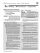
I&
WARNING!
Chillers
or
air
handling
units
:
Install boiler
suc
h
that
-
Chill
ed
me
dimn
,
if
used, is pip
ed
in parallel wi
th
heating boiler. Use
appropr
iate valves
to
prevent
chill
ed
medium from entering boiler. Consult AHRI
Installation a
nd
Pip
in
g Guides.
If
bo
il
er
is
co
nn
ected to heating
co
ils l
oca
t
ed
in
air
handling
units
where they can be exposed
to
refrigerat
ed
air, use
fl
ow
co
nt
ro
l valves
or
o
th
er au-
tomatic
mea
ns
to
preve
nt
gravity
circulatio
n during
coo
li
ng
cycle. Circulation
of
cold water through
the
boiler
could
result in damage
to
the heat exchanger,
causi
ng
possible severe personal injury, death
or
substantial property damage.
Part
Nu
m
ber
550
-
142-7
80/
07
12