
Install Instructions


CG
i
GAS-FIRED
wATER
BOILER-
sERIEs
a-
Boiler
Manual
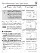
How
it
works
• • •
(!)
Co
nt
ro
l
modul
e
The control module respon
ds
to
signals from the room thermostat, air pressure
sw
itch and bo
il
er
li
mi
t
ci
rcuit to operate
the boiler
ci
rculator,!
il
ot
burner,
gas
valve
and indu
cer.
When room the
rm
ostat calls
fo
r heat, the control module starts the
system circulator an i
nd
ucer.
The control module
nm
s
th
e i
ndu
cer long enough to purge the boiler
flu
e p
assages,
th
en opens the pilot
valve
and activat
es
pilot ignition spark.
For natural gas, the control module
all
ows
up to IS seco
nd
s to establish pilot flam
e.
If
fl
ame is not
se
n
se
d within
IS
seconds,
the control module will turn off
th
e
gas
val
ve,
fla
sh the Flame light, a
nd
then e
nt
er a IS-seco
nd
postpur
ge.
The
co
ntrol module
will
th
en start a new cycl
e.
This will continue indefinitely until p
il
ot
fl
ame is
es
tablished or power is i
nt
errupted. On
ce
pilot
fl
ame
is
pr
ove
n,
th
e
co
ntrol module opens the
gas
va
l
ve
to a
ll
ow ma
in
burner
fl
am
e.
For
pr
opane
gas,
the control m
od
ule a
ll
ows up to IS seco
nd
s to establish pilot
fl
am
e.
If
fl
ame is not
se
nsed within
IS
seconds,
the control module will
tum
off the
gas
val
ve,
fla
sh the Flante
li
ght, wait I mi
nut
e,
th
en start a new cy
cl
e.
If
fl
ame
is
sti
ll
not
se
nsed after the second trial, two more attempts
are
made
wi
th
S mi
nut
e
wai
t periods in between. If
fl
ante
is
not
se
nsed after
4 tries, control w
ill
locko
ut
and
fla
sh a
ll li
ght
s.
Control
mu
st be manually
rese
t
to
place b
ac
k i
nt
o service. On
ce
pilot
fl
ame
is
pr
oven,
th
e
co
ntrol module opens
th
e
gas
val
ve
to a
ll
ow main burner
fl
ant
e.
Whe
n
th
e r
oo
m thermostat
is
sa
ti
sfi
ed, the
co
ntrol m
od
ule turns off the
ga
s val
ve,
operat
es
the i
ndu
cer
fo
r a IS-second
postpurge
and
waits
for the next heat call.
The contr
ol
module indicator lights show normal sequence when the
li
ghts are on steady. When a problem occur
s,
the contr
ol
module
fla
sh
es
combinations of
li
ghts to indicate
th
e most
li
ke
ly reason for the
pr
o
bl
em
(see
page
49).
@ Tran
sf
onner
The contr
ol
transformer reduces
li
ne voltage to
24
volts for the
gas
val
ve
and
li
mit circuit.
@ Inducer
The i
ndu
cer pulls
flu
e g
ases
through the bo
il
er,
cau
si
ng
ai
r to be pulled in
th
ro
ugh the bo
il
er air opening
s.
The indu
ce
r
pu
sh
es
the
flu
e
gases
through
th
e
ve
nt
pipe
as
we
ll
@
Air
pre
ss
ure
switch
The air pressure switch signals the control module, telling the contr
ol
module whether the indu
ce
r is working correctly or
the vent is blocked.
@
Water
temp
e
ratu
re
lim
it s
en
s
or
The
wate
r temperature
li
mit sensor provides a signal to the control module to turn off the gas valve if the temperature in the
boiler
goes
above its settin
g.
(The
ci
rculator w
ill
continue to run as
lo
ng as there is a call for heat.)
@ Boller
ci
rc
ulato
r
The boiler circulator circulates water throu
gh
the
exte
rn
al (system) pipin
g.
The circulator is shipped loose, and can be mounted
on either the boiler supply or return pipin
g.
The factory-installed
ci
rculator wiring harn
ess
provides ample length
fo
r either
location.
NOTE - The contr
ol
module provides a
pu
mp exercising routin
e.
If the boiler is not operated
fo
r
30
days,
the
contr
ol
module
will
power the circulator
fo
r
30
seconds, then tum off.
Ti
mer
rel
ay -
CG
I 4 Only
The timer rel
ays
del
ays
h
igh
fire
fo
r
60
seco
nd
s.
Other
boil
er c
omponen
ts
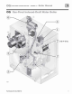
:
2
a supply to system
b return from system
c stainless steel
bu
rners
d
flu
e outlet
e
gas
valve
f pressure/temperature gauge
g relief
valve
h air vent connection
i
fl
ame ro
ll
o
ut
thermal fu
se
eleme
nt
(
TFE)
j burner shield
k pilot
bu
rn
er and bracket
1 gas manifold
m
cast
iron boiler sections
n flue co
ll
ector
o
ju
nction box
Part
Nu
m
ber
550
-
142-7
8
0/07
12