
Install Instructions


CG i
GAS-FIRED
wATER
BOILER-
sERIEs
a-
B
oi
l
er
Manua
l
3f
Venting -
direct
exhaust-
installation
I&
WA
RN
IN
G!
18
1. Do not
mix
types or manufacturers of
ve
nt
materi-
als.
2.
Clea
n all joints before sealing.
See
vent manufac-
turer's
instructions for cleaning and sealing joints.
Us
e their specified sealant.
Do
not
us
e
screws.
3.
In
stall vent pipewithseams on top
of
vent horizon-
tal runs.
Foll
ow requirements in Section
3e
for vent
termination.
4. Maintain mininmm
2"
cl
earan
ce
from combustible
materials to
ve
nt pipe.
5.
Ve
rt
ica
l
venting
-
See
Figure 13.
Fo
ll
ow
ve
nt
manufacturer•s instructions
fo
r venting through
roof.
Vent
pipe must
ex
te
nd
through roof flashin
g,
jacket or thimble.
Vent
may p
ass
through
floor,
inside
wall
or
co
ncealed space when installed according to
vent manufacturees instructions.
Sid
ewa
ll
venUng-
See
Figur
es
14
and
15.
Vent
must temtina
te
at least one foot above
anticipated snowlin
e.
Vent
must be terminated
only with:
Tee
or
elbow with integral screen. (Tee may be
mounted either
vertically or horizontally. DO
N
OT
us
e horizontal t
ee
wi
th
CGi-7
or
CGi-8.)
Elbo
w and termination coupling
wi
th
screen
(not available for
StaR-34).
6. Do not seal
ve
nt
pipe (slip co
nn
ec
tor for Saf-TVent)
to inside
or
outside plate.
7.
If passing through
no
ncombustible wall, provide
hole diameter lar
ge
enough to insert the
ve
nt pipe
(slip connector for
Sa
f-
TV
e
nt
).
8. Install horizontal drain tee as
dose
as possible
to
bo
il
er, in first horizontal run.
See
Figures 13
and
14
.
9. Do not
excee
d the max
in1un1
ve
nt
system length
gi
ven
in
Tab
le 4, page
15.
Condensate drain line- use o
nl
y si
lic
one tubing rated
for
at
least 4
00•
F for
th
e first
18"
of co
nd
ensate drain
li
ne, then other non-metal
lic
tubing may be used. U
s-
ing any o
th
er material
co
uld cause
flu
e
gas
leakage,
potentially resulting in severe personal injury, death or
substantial property dam
age.
On some installations,
th
e condensate drain firting may
be omitted, provided:
Vent
manufacturer
shows
this
option in their instruc-
tions.
Vent
is sloped toward termination
as
shown in dotted
lines in Figure
14
.
The
ve
nt
is installed per WeB-McLain
and
ve
nt
manufacturer's instructions.
Co
nd
ensate drippage
fr
om such
ve
nts may
acaunu
-
late on
th
e gromtd
below.
Consider traffic in
th
e area
to avoid hazard
due
to
ice accu
mu
lation.
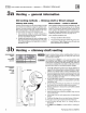
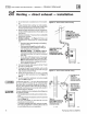
Agure
13
Olrect exhaust vertical venting
Hortzonlal dr
ain
tee
,
Follow
vent
manufocturefs
Instructions
to
Install
condensate dr
ain
line.
Follow
vent
monul
octurefs
fnstruclions for proper
lnstololion
ol
vent
runs,
Including
slope
and
support.
71015
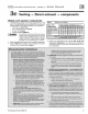
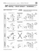
Figure
14
Direct exhaust sidewall vent
in
g
Fdbw
ven
t
\
\
manulacture~s
in
stru
ct
ioo
s
1o<
pro
per
l
ns
1ala
tio
n
of
vent
runs,
i
nclu
ding
slope,
s
~
port
and
oonden
sa
te
drailage
.
L.lJJ
Horizonta
l
drain
tee
.
Rllowwn
t
ma
nula
cwrefs
i
nstr
u
ctio
ns
to
i
nstal
condensate
drain
line.
1
-
O
pt
ional
downward
1
slope
without
drail
1 fi
tti
n
g,
where
alowed
1
by
wnt
man
ufacturer
r
as
expelled In
CPJJnON
at
left.
71
016
Part Number 550-142-780/0712