
Install Instructions


CG i
GAS
-
FIRED
wATER
eo1LER
-
sERIEs
a -
Boiler
Manual
3d
16
Venting -
direct
exhaust -
vent
starter
J.
Select
a
ve
nt
pipe
manufa
ctur
er
and ob
tain
a
ll
vent
components needed, based on boiler location
and
ventmg method.
2.
You
must use t
he
vent starter made by
the
vent
pipe
manufa
cturer.
See
separate CGi, &
GV
Vent
Component
Supp
l
ement,
for
part
number
of
each
component. listed
by
vent manufacturer.
I&
WAR
N
ING
!
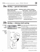
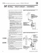
Figure
8
F
as
N
SeaiTM
vent sterter
Figure
9
z-
vent
11
vent starter
Use
only the
ve
nt
starter of the
sa
me
manufacturer as the vent
co
m
po-
nents. Do not
mix
components
from different systems. The ve
nt
sys
tem co
ul
d f
ai
l,
ca
u
sing
flu
e g
as
spillage, resulting in severe personal
i
njury
or death.
6aodclamp
strap
Band
c:la
mp
sc:rew
FasNSeal
""
s
'l
;r;
rter
Blo~t
housing
outlet
71009
Sand
dam
p
sc
rew
~
"Bea
d
of se;,lonl
8!
0\ve
r
hous.ing
ou
tle
t
3.
Follow all applicable national, state, local
or
provin-
cia
l
codes
when
venting
tb
e CGi
boiler.
4. Connect
ve
nt starter to blower housing outlet
as
shown in
the
Figures 8 through
11
.
a.
Do
not
mix
co
mp
onents
from
different
ve
nt
manufacturers.
b. Maintain mini
mum
2"
clearance from
com
..
bustible materials to
ve
nt pipe.
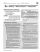
c.
Sea
l witb sealant
specified
by
ve
nt
pipe
manufacturer, using
o/s"
bead
(not required for
Fa
sNSeaf""
).
d. Tighten s
trap
at
band
damp
screw until strap
is
snug
arou
nd blower housing.
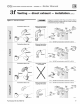
Figure
10
Sal-T
Vent®
vent starter
Figure
11
StaR-
34
vent sta
rter
B;mdc
l
om
p
strap
StoR-34
staner
Part
Number
550
-
142-780/07
12