
Install Instructions


CG
i
GAS
-
FIRED
wATER
BOILER-
sERIEs
a-
B
oi
l
er
Manua
l
1 e Prepare boiler location -
air
openings
I&
WARNING
I
*
Combustion
air
opening
location
and
sizing
requir
ements
depend
on
the
clearances
around
the
boiler. Check
the
bo
iler p
la
cement compared to
Figure
I a, page
7.
If
all
clea
r
ances
are
at
least
equal
to
Figure
1a
,
page
7,
apply the sizing
and
placement
of
opening$
given
on
pages
lO
and
I
I.
If
ANY
clearance
Is
Jess
than
Figure 1
a,
page
7,
yo
u must provide air openings sized and located as
shown in Figure
lb,pa!>e 7.
DO
N
OT
apply
the
s
iz.in
g
and
l
oca
ti
on informa
ti
On
shown on page I 0
or
I
I.
Figure 2
*
Figure 3
Air
openings
must
be
provided *
Combustion air
and
ventilation openings
must
comply the National Fuel
Gas Code
ANS
I Z22
3.
I - latest edition,
or
applicable loc
al
building codes.
Canadian installatio
ns
must comply with Bl49.1
or
Bl49
.2
Installation
Codes.
I&
WARNING
!
Provide adequate combustion
and
ventilation air to
assure proper
combus
ti
on
and
reduce
the
risk
of
severe
personal injur
y,
death
or
substantial property damage
caused by flue gas
sp
illage
and
carbo
n monoxi
de
em
issions.
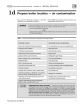
Air
opening
options
TWo
openings -
Air
supply from Inside
the
building *
t.
If
the building is
of
unusually tight construcUon (see definition, next
page), the building
must
also
be
prcwlded with air
openings
dlrecUy
to
the
outside
, sized
and
located per
Fi
gure 3, Figure 4 or Figure 5.
2. Buildings
of
typical construction should
pr
ovide adequate
co
mbustion
air from natural infiltratio
n,
so
additional air openings to the building
are
not
requ
ir
ed.
3.
See Figure 2.
Pr
ovide two
openings
through the i
nt
erior
wa
ll, within
12 inches
of
the
ceiling
and
the
fl
oor, sized
per
Figure 2.
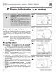
TWo
openings -
Air
supply
directly
from
outside
*
Figure 4
*
I. A
ir
openin
gs
mu
st
be directly through an outside wall,
or
into
a space Figure 5
that connects directly to the outside (such as a ventilated
att
ic
or crawl
space, for example).
2.
See Figure 3-
Openings
directly through
an
outside wall-
_provide
*
two
openings
within 12
in
ches
of
the ceiling
and
the floor,
SIZed
per
Figure
3.
3.
See Figure 4
-Air
supplied
through vertical
ducts
- provide two
openings
terminated within
12
in
ches
of
the
ce
iling
and
the
fl
oo
r, sized
per
Fi
gure
4.
4. See Figure 5 -
Air
supplied
through horizontal
ducts
- provide
two
openings
within 12 inches
of
th
e
fl
oor
and
the ceiling, sized per
Figure
5.
tO
Ai
r openings to Interior
spaces
Ea
ch
opc
ni
i)Q
ff'Oo
u
re
a •
1
sq.
inr.
h per 1,000 lltuh
Air
directly through outside wall
EIIClh
opaning
lr
o•
an:
n =
1
:r;q
. 1nch per 4,000 Btuh
Air
from
outdoo
rs
- vertical
duels
Ou
t
$1
de or v
en
1Ha
1ed a
ulc
E.::lc
h opening Into III'O
ll
a
1 sq. inch
pe
r 4.000 Btuh
• -
...
.. ..
~·
V
cm
!llol<ld
Ull1TJ1lll
Cl'
swt
s
pace
tJUJU:/JJJ
Air
fr
om outdoors - horizontal
duc
ts
Ee
ct.
opening
f;ee ar
ea
'"'
1 sq. lneh p
et
2.0
00
Bt
uh
''"
,
....
Part Number
550-142-780/0712