
Install Instructions
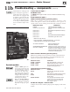


Part Number 550-142-902/1016
CGi
GAS-FIRED WATER BOILER — SERIES 3 — Boiler Manual
51
Troubleshooting — components (continued)
11b
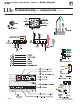
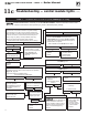
Figure 37 Control module
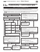
Control indicator lights —
LOCKOUT modes
SeeCharts 1 through 8 in this section for detailed troubleshooting
procedures.
Control indicator lights —
HARD LOCKOUT Summary (Flashing LED’s)
MAY remove 120VAC power for more than 2 seconds to clear
lockout OR ignition control will automatically restart sequence of
operation after 1 hour waiting period after fault condition is cleared.
Control module
Solder or water splatter be-
tween plugs and circuit board
can cause improper operation
of control module. Place a
shield over the boiler inter-
nal controls and components
during installation. Failure to
comply could result in severe
personal injury, death or sub-
stantial property damage.
Make sure ground wiring is
installed per wiring diagram.
Goodgrounding isextremely
important for proper opera-
tion.
The information on this page and
pages 51 through 57 apply only to
spark‑ignited pilot CGi boilers.
These boilers are equipped with
an ignition control module that
has indicator lights to show control
status.Charts1 through 86, pages
53-60, help you identify problems
based on indicator light condi-
tions.
INDICATOR LIGHT CONDITION
POWER
Flashes once per second
120 VAC connection to boiler
reversed or there is insufcient earth
ground.
Flash code 2* Internal fault, microprocessor or memory.
Flash code 3* Unused.
Flash code 4* Unused.
Flash code 5* Internal fault, water thermistors disagree.
Flash code 6*
Flashes once per second
Internal fault, gas valve circuit.
* Flash code pattern: POWER LED ashes 2, 3, etc. times
rapidly followed by 2 seconds off, then repeats.
ALL LED’S FLASHING Failure to establish pilot
ame after 4 attempts.
SOLID SENSOR GROUND LED
and “LCO” on Display
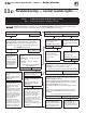
SOFT LOCKOUT Summary (Flashing LED’s)
MAYremove120VACpowerformorethan2seconds,cyclethermostatfor
between 2 and 20 seconds, OR ignition control will automatically restart
sequence of operation after 1 hour waiting period.
INDICATOR LIGHT CONDITION
POWER + TSTAT/CIRC High voltage detected on TSTAT circuit.
POWER + PURGE Pressure Switch stuck open or closed.
POWER + FLAME Flame sensed without call for heat or out
of sequence during ignition trial.
CAUTION Summary (Flashing LED’s)
INDICATOR LIGHT CONDITION
PURGE Pressure switch opened after it had been
proven closed.
LIMIT Fault detected in temperature sensing hardware.
FLAME Flame loss or ame not sensed during
trial for ignition.
SENSOR GROUND Three (3) rapid pulses indicates the sensor
ground wire may not be connected or the
boiler has a poor ground connection or
stray voltage on ground.
Troubleshooting the control module
SeeFigure38,forlocationofharnessplugreceptaclesandplugsonthecontrol
module.
Indicates the sensor ground wire is not
grounded or the boiler has a poor ground
connection or stray voltage on ground.
Check both sensor ground wire on the P5
connection and the boiler ground.