
Install Instructions


Part Number 550-142-902/1016
CGi
GAS-FIRED WATER BOILER — SERIES 3 — Boiler Manual
50
Troubleshooting — components (continued)
11a
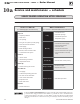
Sensor resistance values
Temp
(°F)
Sensor ohms
Temp
(°F)
Sensor ohms
Min Max Min Max
32
34265 37871
120
4517 4992
40
27834 30764
130
3698 4088
50
21630 23907
140
3043 3364
60
16944 18727
150
2517 2782
70
13372 14780
160
2091 2311
80
10629 11747
170
1744 1928
90
8504 9399
180
1461 1615
100
6847 7568
190
1229 1359
110
5545 6129
200
1038 1147
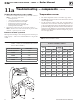
Temperature sensor
1. The boiler temperature sensor is a resistance-type device.
2. The Table 10, below shows the correct value for the sensor at
various temperatures.
3. Use the resistance values at 32°F, 60°F, 70°F and 212°F to
measure the sensor resistance at known temperatures (ice
point, room temperature and sea level boiling point). For ice
point and boiling point, insert the sensor in water at that tem-
perature. Use an ohmmeter to read resistance value between
thermistor#andthermistorcommon.SeeFigure38,page 52,
for sensor plug details.
Table 10 Sensor resistance values
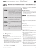
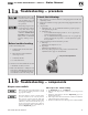
Troubleshooting air pressure reading
1. If manometer reading is lower than the setpoint of the switch (see
Table 9
) — check for possible causes:
• blockageinhoses
• obstructionininducerhousingoutlet
• looseinducerwheelonmotorshaft
• inducermotornotinproperrpm
• inducerbackplatenotsealedproperly
• blockageinblockassembly
2. If manometer reading is above the setpoint of the switch (see
Table 9),butthereisnot24VAC betweenbothairpressureswitch
terminals — replace air pressure switch.
Return to normal operation
When pressure reading is correct and air pressure switch is oper-
ating properly — remove tees and reinstall hoses to air pressure
switch.
Figure 36 Manometer connections
Table 9 Pressure switch setpoint (for elevations above
2,000 ft., contact your local Weil-McLain Technical
Service office for details.)
Boiler model number Inches W.C.
CGi-25 and CGi-3
1.79
CGi-4
1.36
CGi-5
1.12
CGi-6 and CGi-8
0.80
CGi-7
0.75