
Install Instructions


Part Number 550-142-902/1016
CGi
GAS-FIRED WATER BOILER — SERIES 3 — Boiler Manual
49
Troubleshooting — procedure
11a
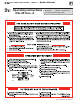
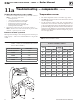
Air pressure switch
Makesureboilerwatertemperatureis100°F
or cooler before starting procedure to obtain
appropriate readings.
The boiler will not operate correctly unless
pressure switch hoses are correctly located.
The red hose connects from the right side
(negative) hose barb to the flue collector. The
white hose connects from the left side (posi-
tive) hose barb of the switch to the connector
box (between flue collector and inducer) as
shown in Figure 36, page 50.
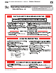
Check pressure switch setting
1. SeeFigure 36, page 50, and Table 9.
2. Remove both air pressure switch hoses from air pressure
switch.
3. Install tees and tubing as shown in Figure 36, page 50, to
inclined manometer.
4. Turn off gas valve and set thermostat to call for heat. Inducer
will run but burners will not ignite.
5. Checkfor24VAC betweenbothairpressureswitchterminals.
Troubleshooting — components
11b
Labelallwirespriortodis-
connection when servicing
controls. Wiring errors can
cause improper and danger-
ous operation.
Neverjumper(bypass)roll-
out thermal fuse element
or any other device except
for momentary testing as
outlined in
Troubleshoot-
ing Charts
.Severepersonal
injury, death or substantial
property damage can re-
sult.
Before troubleshooting:
1. Havethefollowingitems:
a. Voltmeterthatcancheck120VAC
and24VAC .
b. Microammeterwithaminimum
scale range of 0-25.
c. Continuitychecker.
d. U-tube manometer.
2. Checkfor120VAC (minimum102VAC
tomaximum132VAC ) toboiler.
3. Makesurethermostatiscallingforheat
and contacts (including appropriate zone
controls)areclosed.Checkfor24VAC be-
tween thermostat wire nuts and ground.
Check the following:
1. Wire connectors to control module are securely plugged in at module and
originating control.
2. Airpressureswitchhosesareproperlyandsecurelypluggedinandarenot
damaged.
3. Gaspressures:
a. Withboileroff—13”w.c.maximumnaturalorpropanegaspres-
sure upstream of gas valve.
b. With boiler on:
• 5”w.c.minimumnaturalgaspressureor11”w.c.propanegas
pressure upstream of gas valve.
• 3½”w.c.minimumnaturalgaspressureor10”w.c.propanegas
pressuredownstreamofgasvalve—Canbeadjustedbyregula-
tor on gas valve.
4. Verify gas manifold pressure (downstream of gas valve):
a. Natural gas:
Manifold pressure, high fire: 3.50” w.c.
b. Propane gas:
Manifold pressure, high fire: 10.0” w.c.
c. If necessary, adjust gas pressure on the gas valve as shown below. After
adjustments, refer to page 35 to check the flame.
Gas pressure adjustment