
Install Instructions


Part Number 550-142-902/1016
CGi
GAS-FIRED WATER BOILER — SERIES 3 — Boiler Manual
38
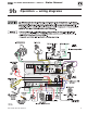
Operation — sequence (continued)
9a
— The circulator continues to operate.
8. Lower room thermostat setting to stop call for heat. Thermostat is satisfied — Pilot and main gas valves are
closed—Induceroperatesfor15‑secondpostpurge—Circulatorisshutoff.
9. Boilerisnowintheoff cycle.
10. Repeat steps 1 through 6 several times to verify operation.
11. Return the thermostat to normal setting.
12.SetthermostatheatanticipatorsettingasinstructedinFigure 32, page 40.
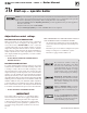
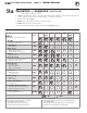
Figure 30 Control module sequence of operation — status light indications
STEPS
(following step 9, cycle goes back to step 1.)
Call for
Heat?
POWER TSTAT
CIRC
LIMIT PURGE FLAME SENSOR
GND
Timing
1. Standby
• Waiting for call for heat
NO
—
2. Call for heat
• Circulatoron
YES —
3. Limit circuit
• Limitcontrolsclosed
• Rollout TFE contacts closed
YES
—
4. Inducer
• Inducer turns on
YES
—
5. Pressure circuit
• Pressure switch contacts closed
• Prepurge for 10 seconds
YES
35
sec
6. Flame proven *
• Gasvalveopen
• Ignitor remains on
• Boilerproducingheat
YES
15
sec
7. Limit cycle
• Limitcircuitopen
• Gasvalveclosed
YES
—
8. Flame outage *
• Flame out
• Boilerrecycles
YES
—
9. Thermostat satised
• Circulatoroff
NO
15
sec
10. Circulator exercise routine
• Circulatorturnsonfor30 seconds if
boiler not operated for 30 days
NO
30
sec
11. Sensor ground
• Sensorgroundcircuitopen
YES/NO —
= ON
= OFF
* See Section 9, Items 4b for controls response to failure to prove pilot ame.
Control will lockout under the following conditions:
• Line voltage polarity is reversed
• Stray voltage is sensed on thermostat line
• Flame is sensed when it shouldn’t be there
Control will reset after these lockouts if any of the following occur:
• 1 hour waiting period
• Opening and closing of thermostat circuit for 2 to 20 seconds
• Removal of 120 VAC power for 2 to 20 seconds