
Install Instructions


Part Number 550-142-902/1016
CGi
GAS-FIRED WATER BOILER — SERIES 3 — Boiler Manual
31
Field wiring
6
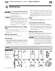
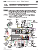
Figure 27
Field wiring connec-
tions —
service switch, DHW
(if used) and
thermostat
(or end switch)
provided by installer
For your safety, turn off electrical power supply
at service entrance panel before making any
electrical connections
to avoid possible electric
shock hazard. Failure to do so can cause severe
personal injury or death.
Wiring must be N.E.C. Class 1.
If original rollout thermal fuse element wire as
supplied with boiler must be replaced, use only
type 200°C wire or equivalent. If other original
wiring as supplied with boiler must be replaced,
type 105°C wire or equivalent must be used.
Boilermustbe
electrically grounded as required
by National Electrical CodeANSI/NFPA 70 –
latest edition.
Electrical installation must comply
with:
1. NationalElectricalCodeandanyothernational,state,pro-
vincial or local codes or regulations.
2. InCanada,CSAC22.1CanadianElectricalCodePart1,and
any local codes.
Wiring connections
Boilerisshippedwithcontrolscompletelywired.
Thermostat
1. Connectthermostatasshownonwiringdiagramonboiler.
2. Install on inside wall away from influences of drafts, hot
or cold water pipes, lighting fixtures, television, sun rays,
or fireplaces.
3. If thermostat has a heat anticipator, set heat anticipator in
thermostat to match power requirements of equipment con-
nected to it. If connected directly to boiler, set for 0.1 amps
plusgasvalvecurrent.Seeinformationonwiringdiagram
as shown in
Figure 32, page 39. For other devices, refer to
manufacturer’s specifications. Wiring diagram on boiler gives
settingforcontrolmoduleandgasvalve.Alsoseeinstructions
with thermostat.
DHW
1. ConnectDHWaquastatasshowninwiringbelow.Economy
functionisn’tutilizedwithDHWinput.
Junction Box (furnished)
1. Connect120VACpowerwiringasshowninFigure 27.
2. Fused disconnect or service switch (15 amp. recommended)
may be mounted on this box. For those installations with
local codes which prohibit installation of fused disconnect
or service switch on boiler, install a 2 x 4 cover plate on the
boiler junction box and mount the service switch remotely
as required by the code.
Wiring multiple zones
Refer to zone valve manufacturer’s literature for wiring and ap-
plication.Aseparatetransformerisrequiredtopowerzonevalves.
Zoningwithcirculatorsrequiresarelayforeachcirculator.
DO NOT connect directly from 3-wire zone
valves to the T-T terminals on the boiler
.
When using 3-wire zone valves, install an isolation
relay.Connectthezonevalveendswitchwiresto
theisolationrelaycoil.Connecttheisolationrelay
contact across the boiler T-T terminals. Failure to
comply can result in damage to boiler components
or cause unreliable operation, resulting in severe
property damage.
TheCGicontrolmoduleispolarity‑sensitive.Thehotandneutralwiresmustbeconnectedtothecorrectleads.
AashingPOWER lightusuallyindicatesreversedpolarityof120VAC leadwires.