
Install Instructions


Part Number 550-142-902/1016
CGi
GAS-FIRED WATER BOILER — SERIES 3 — Boiler Manual
27
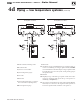
Piping — low temperature systems (continued)
4d
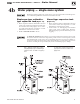
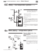
1 Boilerisolation(balancing)valves
2 Flow/check valve
3 Systemorzonecirculator
4 Systemtemperaturegauges
5 Zonevalve
6 Drainvalve
7 System temperaturevalves (see in-
structions to the left for adjusting
valves)
8 Blend temperature gauge
9 Relief valve
10Automaticairvent(withdiaphragm‑typeexpansiontank),or
connect to tank fitting (closed-type expansion tank). DO NOT use
an automatic air vent when using closed-type expansion tank. It
would allow air to leave the system, causing waterlogging of the
expansion tank.
11 Fill valve
12Diaphragm‑typeorbladder‑typeexpansiontank,ifused(For
closed-type expansion tank, pipe from top of air separator to
tank fitting as in Figure 17, page 21).
13Air separator and automatic vent, if used (Note that the ll valve
must always be connected to the expansion tank, regardless of
location of expansion tank, circulator or air separator.)
Figure 22 Boiler-bypass piping — Zoning with
circulators — (Alternative to primary/
secondary piping Figures 20 and 21)
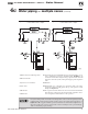
Figure 23 Boiler-bypass piping — Zoning with
zone valves — (Alternative to primary/
secondary piping Figures 20 and 21)