
Install Instructions


Part Number 550-142-902/1016
CGi
GAS-FIRED WATER BOILER — SERIES 3 — Boiler Manual
18
Venting — direct exhaust — installation
3f
1. Donotmixtypesormanufacturersofventmateri-
als.
2. Cleanalljointsbeforesealing.Seeventmanufac-
turer’s instructions for cleaning and sealing joints.
Usetheirspeciedsealant.Donotusescrews.
3. Install vent pipe with seams on top of vent horizon-
talruns.FollowrequirementsinSection3e for vent
termination.
4. Maintainminimum2”clearancefromcombustible
materials to vent pipe.
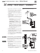
5. Vertical venting— See Figure 13. Follow vent
manufacturer’s instructions for venting through
roof.
• Ventpipemustextendthroughroofashing,
jacket or thimble.
• Ventmaypassthroughoor,insidewallor
concealed space when installed according to
vent manufacturer’s instructions.
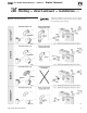
Sidewall venting—SeeFigures 14 and 15.
Vent mustterminateatleastonefootabove
anticipatedsnowline.Ven tmustbeterminated
only with:
• Tee orelbowwithintegralscreen.( Te e maybe
mounted either vertically or horizontally. DO
NOT
usehorizontalteewithCGi‑7orCGi‑8.)
• Elbowandterminationcouplingwithscreen
(notavailableforStaR‑34).
6. Donotsealventpipe(slipconnectorforSaf‑TVent)
to inside or outside plate.
7. If passing through noncombustible wall, provide
hole diameter large enough to insert the vent pipe
(slipconnectorforSaf‑TVent).
8. Install horizontal drain tee as close as possible to
boiler,inrsthorizontalrun.SeeFigures 13 and 14.
9. Do not exceed the maximumventsystem length
given in Table 4, page 15.
Condensatedrainline—useonly siliconetubingrated
foratleast400°Ffortherst18”ofcondensatedrain
line, then other non-metallic tubing may be used. Us-
ing any other material could cause flue gas leakage,
potentially resulting in severe personal injury, death or
substantial property damage.
On some installations, the condensate drain fitting may
be omitted, provided:
• Vent manufacturershowsthisoptionintheirinstruc-
tions.
• Vent isslopedtowardterminationasshownindotted
lines in Figure 14.
• The vent is installed per Weil‑McLain and vent
manufacturer’s instructions.
• Condensatedrippagefromsuchventsmayaccumu-
lateonthegroundbelow.Considertrafcinthearea
to avoid hazard due to ice accumulation.
Figure 13 Direct exhaust vertical venting
Figure 14 Direct exhaust sidewall venting