Beginning Serial Number: CP7531680 Series 3 Gas-Fired Water Boilers Boiler Manual • Installation • Maintenance • Startup • Parts * *Blower cover on sizes CGi 25-5 only DO NOT USE BOILER DURING CONSTRUCTION unless you provide dust-free air to the boiler area or follow the requirements given on page 9. Failure to comply could result in severe personal injury, death or substantial property damage. This manual must only be used by a qualified heating installer/service technician.
CGi GAS-FIRED WATER BOILER — SERIES 3 — Boiler Manual How it works . . . ① ② ③ ④ ⑤ ⑥ Control module The control module responds to signals from the room thermostat, air pressure switch and boiler limit circuit to operate the boiler circulator, pilot burner, gas valve and inducer. When room thermostat calls for heat, the control module starts the system circulator and inducer.
CGi GAS-FIRED WATER BOILER — SERIES 3 — Boiler Manual CGi Gas-Fired Induced-Draft Water Boiler Part Number 550-142-902/1016 3
CGi GAS-FIRED WATER BOILER — SERIES 3 — Boiler Manual Contents How it works . . . ................................................. 2 Hazard definitions ............................................... 4 Please read before proceeding ............................ 5 1 Prepare boiler location ...................................6–11 2 Prepare boiler...............................................12–13 3 Venting ......................................................... 14-19 4 Water piping .................
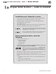
CGi GAS-FIRED WATER BOILER — SERIES 3 — Boiler Manual Please read before proceeding Installer User Read all instructions before installing. Fol- • • low all instructions in proper order to prevent personal injury or death. Consider piping and installation when determining boiler location. Any claims for damage or shortage in shipment must be filed immediately against the transportation company by the consignee. • This manual is for use only by your qualified heating installer/service technician.
CGi GAS-FIRED WATER BOILER — SERIES 3 — Boiler Manual 1a Prepare boiler location — codes & checklist Installations must follow these codes: • • • • • Local, state, provincial, and national codes, laws, regulations and ordinances. National Fuel Gas Code, ANSI Z223.1/NFPA 54 –– latest edition. Standard for Controls and Safety Devices for Automatically Fired Boilers, ANSI/ASME CSD‑1, when required. National Electrical Code. For Canada only: B149.1 or B149.
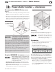
CGi GAS-FIRED WATER BOILER — SERIES 3 — Boiler Manual 1b Prepare boiler location — clearances Recommended SERVICE clearances Figure 1b Required MINIMUM clearances (Fig. 1a) 1. Provide clearances for cleaning and servicing the boiler and for access to controls and components. See Figure 1a for recommendations. 2. Provide at least screwdriver clearance to jacket front panel screws for removal of front panel for inspection and minor service.
CGi GAS-FIRED WATER BOILER — SERIES 3 — Boiler Manual 1c Prepare boiler location — vent system Failure to follow all instructions can result in flue gas spillage and carbon monoxide emissions, causing severe personal injury or death. Inspect existing chimney before installing boiler. Failure to clean or replace perforated pipe or tile lining will cause severe personal injury or death. Direct exhaust venting (Category III) — DO NOT COMMON vent the CGi in a direct exhaust system (Category III).
CGi GAS-FIRED WATER BOILER — SERIES 3 — Boiler Manual 1d Prepare boiler location — air contamination Please review the following information on potential combustion air contamination problems. Refer to Table 1 for products and areas which may cause contaminated combustion air. To prevent potential of severe personal injury or death, check for products or areas listed below before installing boiler.
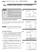
CGi GAS-FIRED WATER BOILER — SERIES 3 — Boiler Manual 1e Prepare boiler location — air openings Combustion air opening location and sizing requirements depend on the clearances around the boiler. Check the boiler placement compared to Figure 1a, page 7. ✷ Figure 2 Air openings to interior spaces ✷ If all clearances are at least equal to Figure 1a, page 7, apply the sizing and placement of openings given on pages 10 and 11.
CGi GAS-FIRED WATER BOILER — SERIES 3 — Boiler Manual 1e Prepare boiler location — air openings FREE AREA of openings — the minimum areas given in this manual are free area (equals the area, length times width of opening, after deduction for louver obstruction). Use the free area information provided by the louver manufacturer.
CGi GAS-FIRED WATER BOILER — SERIES 3 — Boiler Manual 2a Prepare boiler — placement & setup Place boiler/crate near position 1. Leave boiler in shipping carton and on pallet until installation site is ready. 2. Move entire shipping carton and pallet next to selected location. 3. Remove shipping carton. 4. Remove boiler from pallet. Do not drop boiler or bump jacket on floor or pallet. Damage to boiler can result. a. Tilt left side of boiler up and place a board under left legs. b.
CGi GAS-FIRED WATER BOILER — SERIES 3 — Boiler Manual 2b Prepare boiler — pressure test Hydrostatic pressure test Pressure test boiler before attaching water or gas piping (except as noted below) or electrical supply. Prepare boiler for test 1. Remove the shipping nipple (from CGi supply tapping) and remove the boiler relief valve. Temporarily plug the relief valve tapping with a ¾” NPT pipe plug. 2.
CGi GAS-FIRED WATER BOILER — SERIES 3 — Boiler Manual 3a Venting — general information CGi venting methods — Chimney draft or Direct exhaust Chimney draft venting Chimney draft venting uses the natural draft provided by a vertical vent or chimney. Category I appliance (non‑ positive vent static pressure and vent gas temperature that avoids excessive condensate production in vent). See Section 3b. Chimney draft installations use: 1.
CGi GAS-FIRED WATER BOILER — SERIES 3 — Boiler Manual 3c Venting — Direct exhaust — components Obtain vent system components 1. The following special gas vent systems comply with UL‑1738 and ULC‑S636 standards and are certified by CSA as the only systems suitable for use with CGi boilers (all 3” diameter): • Heat‑Fab, Inc. Saf-T Vent® • Flex‑L International, Inc. StaR-34 • Z‑Flex®, Inc. Z-Vent II • ProTech Systems FasNSeal™ Use only the vent starter of the same manufacturer as the vent components.
CGi GAS-FIRED WATER BOILER — SERIES 3 — Boiler Manual 3d Venting — direct exhaust — vent starter 1. Select a vent pipe manufacturer and obtain all vent components needed, based on boiler location and venting method. 2. You must use the vent starter made by the vent pipe manufacturer. See separate CGi, & GV Vent Component Supplement, for part number of each component, listed by vent manufacturer. Use only the vent starter of the same manufacturer as the vent components.
CGi GAS-FIRED WATER BOILER — SERIES 3 — Boiler Manual 3e Venting — direct exhaust — termination The vent termination must be located to meet all requirements below (also applies to vertical vent terminations). The minimum distance from adjacent public walkways, adjacent buildings, openable windows and building in the National Fuel Gas Code, ANSI Z223.1/NFPA 54 and/or the Natural Gas and Propane Installation Code, CAN/CSA B149.1. The vent termination clearances below are for U.S.A.
CGi GAS-FIRED WATER BOILER — SERIES 3 — Boiler Manual 3f Venting — direct exhaust — installation 1. Do not mix types or manufacturers of vent materials. 2. Clean all joints before sealing. See vent manufacturer’s instructions for cleaning and sealing joints. Use their specified sealant. Do not use screws. 3. Install vent pipe with seams on top of vent horizontal runs. Follow requirements in Section 3e for vent termination. 4. Maintain minimum 2” clearance from combustible materials to vent pipe. 5.
CGi GAS-FIRED WATER BOILER — SERIES 3 — Boiler Manual 3f Figure 15 Venting — direct exhaust — installation Sidewall termination Part Number 550-142-902/1016 (cont.) Using any termination other than one of those shown could cause nuisance outages and loss of heat, resulting in substantial property damage.
CGi GAS-FIRED WATER BOILER — SERIES 3 — Boiler Manual 4a Water piping — general information General piping information Circulator If installation is to comply with ASME or Canadian requirements, an additional high temperature limit maybe needed. Install control in supply piping between boiler and isolation valve. Set second control to minimum 20°F above setpoint of first control. Maximum allowable setpoint is 240°F. See Section 9b for wiring.
CGi GAS-FIRED WATER BOILER — SERIES 3 — Boiler Manual 4b Water piping — single-zone system Undersized expansion tanks cause system water to be lost from relief valve and makeup water to be added through fill valve. Eventual section failure can result. Diaphragm-type or bladdertype expansion tank (Figure 16) 1. Ensure expansion tank size will handle boiler and system water volume and temperature. Tank must be located in boiler return piping as close to boiler as possible, before inlet side of circulator.
CGi GAS-FIRED WATER BOILER — SERIES 3 — Boiler Manual 4c Water piping — multiple zones Piping multiple zones Follow instructions on pages 20 and 21 to install nearboiler or single‑zone piping. (Also refer to Piping for radiant heating systems or converted gravity systems, below, if applicable.) See Figure 18 or Figure 19 to complete installation. Zoning with circulators (Figure 18) (return temp over 130°F) 1. Size each circulator to individual circuit requirements. 2.
CGi GAS-FIRED WATER BOILER — SERIES 3 — Boiler Manual 4c Water piping — multiple zones Figure 18 Figure 19 Zoning with circulators — return water 130°F or higher. 1 Boiler isolation (balancing) valves 2 Flow/check valve (continued) Zoning with zone valves — return water 130°F or higher. 10 Automatic air vent (with diaphragm‑type expansion tank), or connect to tank fitting (closed-type expansion tank). DO NOT use an automatic air vent when using closed-type expansion tank.
CGi GAS-FIRED WATER BOILER — SERIES 3 — Boiler Manual 4d Piping — low temperature systems Primary/secondary (preferred) bypass piping method Primary/secondary bypass piping is preferred because the flow rate and temperature drop in the heating circuit(s) is determined only by the heating circuit circulator(s). So adjustment of the bypass valves in the boiler circuit will not cause a change in the heating circuit rate and temperature distribution.
CGi GAS-FIRED WATER BOILER — SERIES 3 — Boiler Manual 4d Piping — low temperature systems Figure 20 Primary/secondary piping Zoning with circulators 1 Boiler isolation (balancing) valves 2 Flow/check valve 3 System or zone circulator 4 System temperature gauges 5 Zone valve 6 Drain valve 7 System temperature valves (see instruc- tions to the left for adjusting valves) 8 Blend temperature gauge Part Number 550-142-902/1016 Figure 21 (continued) Primary/secondary piping Zoning with zone valves 9 R
CGi GAS-FIRED WATER BOILER — SERIES 3 — Boiler Manual 4d Piping — low temperature systems BOILER-bypass piping method This piping method (Figure 22 or 23) is called a boilerbypass because part of the circulator flow is bypassed around the boiler (through valve 7a). This method reduces the flow rate throughout the boiler, in order to raise the average water temperature in the boiler enough to prevent flue gas condensation.
CGi GAS-FIRED WATER BOILER — SERIES 3 — Boiler Manual 4d Piping — low temperature systems Figure 22 Boiler-bypass piping — Zoning with circulators — (Alternative to primary/ secondary piping Figures 20 and 21) 1 Boiler isolation (balancing) valves 2 Flow/check valve 3 System or zone circulator 4 System temperature gauges Figure 23 (continued) Boiler-bypass piping — Zoning with zone valves — (Alternative to primary/ secondary piping Figures 20 and 21) 9 Relief valve 10 Automatic air vent (with diap
CGi GAS-FIRED WATER BOILER — SERIES 3 — Boiler Manual 4d Piping — low temperature systems SYSTEM-bypass piping method This piping method is called a system-bypass because part of the circulator flow bypasses the system (through valve 7a). This bypassed hot water from the boiler outlet mixes with cooler system return water temperature in order to provide minimum 130°F return water to the boiler.
CGi GAS-FIRED WATER BOILER — SERIES 3 — Boiler Manual 4d Piping — low temperature systems Figure 24 (continued) System-bypass piping — Zoning with zone valve or circulators, return water 130°F or higher — (Alternative to boilerbypass piping Figures 22 and 23) 3 System or zone circulator 7 System temperature valves (see instructions to the left for adjusting valves) 8 Blend temperature gauge 9 Relief valve 10 Automatic air vent (with diaphragm‑type expansion tank), or connect to tank fitting (closed-ty
CGi GAS-FIRED WATER BOILER — SERIES 3 — Boiler Manual 5 Gas piping Connecting gas supply piping to boiler 1. Remove jacket front panel and refer to Figure 26 to pipe gas to boiler. a. Install drip leg at inlet of gas connection to boiler. Where local utility requires drip leg to be extended to the floor, use appropriate length of pipe between cap and tee. b. Install ground joint union for servicing, when required. c.
CGi GAS-FIRED WATER BOILER — SERIES 3 — Boiler Manual 6 Field wiring For your safety, turn off electrical power supply at service entrance panel before making any electrical connections to avoid possible electric shock hazard. Failure to do so can cause severe personal injury or death. Wiring must be N.E.C. Class 1. If original rollout thermal fuse element wire as supplied with boiler must be replaced, use only type 200°C wire or equivalent.
CGi GAS-FIRED WATER BOILER — SERIES 3 — Boiler Manual 7a Start-up — preparation Check for gas leaks Before starting the boiler, and during initial operation, smell near the floor and around the boiler for gas odorant or any unusual odor. Do not proceed with start-up if there is any indication of a gas leak. Repair any leak at once. Propane boilers only — Your pro- pane supplier mixes an odorant with the propane to make its presence detectable.
CGi GAS-FIRED WATER BOILER — SERIES 3 — Boiler Manual 7a Start-up — preparation (continued) Fill the system with water Inspect system water piping 1. Close manual and automatic air vents and boiler drain cock. After filling the boiler and system with water, inspect all piping throughout the system for leaks. If found, repair 2. Fill to correct system pressure. Correct pressure will vary with each application. Typical cold water fill pressure for a residential system is 12 psi. 3.
CGi GAS-FIRED WATER BOILER — SERIES 3 — Boiler Manual 7b Start-up — operate boiler DO NOT proceed with boiler operation unless boiler and system have been filled with water and all instructions and procedures of previous manual sections have been completed. Failure to do so could result in severe personal injury, death or substantial property damage.
CGi GAS-FIRED WATER BOILER — SERIES 3 — Boiler Manual 7b Start-up — operate boiler (continued) Start the boiler • • Follow the Operating instructions from Section 9c to start the boiler. See Section 7c if boiler fails to start. Check system and boiler Main burner flame (Figure 29) PROPER main burner flame characteristics 1. Yellow‑orange streaks may appear (caused by dust). IMPROPER main burner flame characteristics 1. Check system piping for leaks. If found, shut down boiler and repair immediately.
CGi GAS-FIRED WATER BOILER — SERIES 3 — Boiler Manual 8 ❏ ❏ ❏ ❏ ❏ ❏ ❏ ❏ ❏ ❏ Check-out procedure — checklist Boiler and heat distribution units filled with water? Automatic air vent, if used, open one full turn? Air purged from system? Air purged from gas piping? Piping checked for leaks? Correctly sized manifold orifices installed? Refer to Table 2, page 12, to check size and fuel type. Correctly sized manifold orifices must be used.
CGi GAS-FIRED WATER BOILER — SERIES 3 — Boiler Manual 9 Department of Energy – Compliance This boiler is equipped with a control system that automatically adjusts a time delay period to turn on the boiler during a call for heat. This is accomplished by circulating available hot water in the system while measuring water boiler water temperature changes.
CGi GAS-FIRED WATER BOILER — SERIES 3 — Boiler Manual 9a Figure 30 Operation — sequence (continued) — The circulator continues to operate. 8. Lower room thermostat setting to stop call for heat. Thermostat is satisfied — Pilot and main gas valves are closed — Inducer operates for 15‑second postpurge — Circulator is shut off. 9. Boiler is now in the off cycle. 10. Repeat steps 1 through 6 several times to verify operation. 11. Return the thermostat to normal setting. 12.
CGi GAS-FIRED WATER BOILER — SERIES 3 — Boiler Manual 9b Figure 31 Operation — wiring diagrams Schematic wiring diagram Part Number 550-142-902/1016 39
CGi GAS-FIRED WATER BOILER — SERIES 3 — Boiler Manual 9b Figure 32 40 Operation — wiring diagrams (continued) Ladder wiring diagram Part Number 550-142-902/1016
CGi GAS-FIRED WATER BOILER — SERIES 3 — Boiler Manual instructions 9c Operating CGi-25 thru -6 Part Number 550-142-902/1016 • Spark pilot • Natural or propane gas • Gas valve: Honeywell VR8204/VR8304 41
CGi GAS-FIRED WATER BOILER — SERIES 3 — Boiler Manual 9c 42 Operating instructions CGi-25 thru -6 • Spark pilot • Natural or propane gas • Gas valve: White-Rodgers 36E Part Number 550-142-902/1016
CGi GAS-FIRED WATER BOILER — SERIES 3 — Boiler Manual 9c Operating instructions CGi-25 thru -8 Part Number 550-142-902/1016 • Spark pilot • Natural or propane gas • Gas valve: White-Rodgers 36C 43
CGi GAS-FIRED WATER BOILER — SERIES 3 — Boiler Manual 10a Service and maintenance — schedule VERIFY PROPER OPERATION AFTER SERVICING Table 8 Service and maintenance schedules Service technician Owner maintenance (see following pages for instructions) (see CGi User’s Information Manual for instructions) • Check boiler area Inspect: • Reported problems Daily • Boiler area • Check air openings • Check boiler pressure temperature gauge • Air openings • Flue gas vent system (and air piping) • Check
CGi GAS-FIRED WATER BOILER — SERIES 3 — Boiler Manual 10b Service and maintenance — annual start-up 2. Verify that boiler vent discharge is clean and free of obstructions. The boiler should be inspected and started annually, at the beginning of the heating season, only by a qualified service technician. In addition, the maintenance and care of the boiler designated in Table 8, page 44, and explained on the following pages must be performed to assure maximum boiler efficiency and reliability.
CGi GAS-FIRED WATER BOILER — SERIES 3 — Boiler Manual 10b ❏ Service & maintenance – annual start-up Inspect . . . Burners and base 4. Reinstall components, starting with the burner tray, then the pilot bracket assembly, burner baffle, and air inlet top and front panels. 5. Follow the start-up procedure in the boiler manual. The boiler contains ceramic fiber and fiberglass materials. Use care when handling these materials per instructions on page 71 of this manual.
CGi GAS-FIRED WATER BOILER — SERIES 3 — Boiler Manual 10b ❏ Service & maintenance – annual start-up Check/test . . . Gas piping (cont.) Open-type — located above highest radiator or baseboard unit, usually in the attic or closet. Has a gauge glass and overflow pipe to a drain. 1. Sniff near floor and around boiler area for any indication of a gas leak. 2. Test gas piping using bubble test, per Section 5 of this manual, if there is any indication of a leak.
CGi GAS-FIRED WATER BOILER — SERIES 3 — Boiler Manual 10b Service & maintenance – annual start-up (cont.) Safety relief valves should be reinspected AT LEAST ONCE EVERY THREE YEARS, by a licensed plumbing contractor or authorized inspection agency, to ensure that the product has not been affected by corrosive water conditions and to ensure that the valve and discharge line have not been altered or tampered with illegally.
CGi GAS-FIRED WATER BOILER — SERIES 3 — Boiler Manual 11a Troubleshooting — procedure Label all wires prior to disconnection when servicing controls. Wiring errors can cause improper and dangerous operation. Never jumper (bypass) rollout thermal fuse element or any other device except for momentary testing as outlined in Troubleshooting Charts. Severe personal injury, death or substantial property damage can result. Before troubleshooting: 1. Have the following items: a.
CGi GAS-FIRED WATER BOILER — SERIES 3 — Boiler Manual 11a Troubleshooting — components Troubleshooting air pressure reading 1. If manometer reading is lower than the setpoint of the switch (see Table 9) — check for possible causes: • • • • • • blockage in hoses obstruction in inducer housing outlet loose inducer wheel on motor shaft inducer motor not in proper rpm inducer back plate not sealed properly blockage in block assembly 2.
CGi GAS-FIRED WATER BOILER — SERIES 3 — Boiler Manual 11b Troubleshooting — components The information on this page and pages 51 through 57 apply only to spark‑ignited pilot CGi boilers. These boilers are equipped with an ignition control module that has indicator lights to show control status. Charts 1 through 86, pages 53-60, help you identify problems based on indicator light conditions.
CGi GAS-FIRED WATER BOILER — SERIES 3 — Boiler Manual 11b Figure 38 52 Troubleshooting — components (continued) Control module connections Part Number 550-142-902/1016
CGi GAS-FIRED WATER BOILER — SERIES 3 — Boiler Manual 11c Troubleshooting — control module lights CHART 1 –– Troubleshooting POWER light status –– Usually indicates reversed 120 VAC polarity if POWER light flashes by itself –– 120 Electrical shock hazard — Wherever you see ▲ TURN OFF POWER ▲, follow the instructions. Failure to follow instructions could result in severe personal injury, death or substantial property damage.
CGi GAS-FIRED WATER BOILER — SERIES 3 — Boiler Manual 11c Troubleshooting — control module lights (cont.) CHART 2 –– TSTAT CIRC & POWER light flashing –– Usually indicates 48 VAC on thermostat circuit (stray voltage) –– 120 Electrical shock hazard — Wherever you see ▲ TURN OFF POWER ▲, follow the instructions. Failure to follow instructions could result in severe personal injury, death or substantial property damage.
CGi GAS-FIRED WATER BOILER — SERIES 3 — Boiler Manual 11c Troubleshooting — control module lights (cont.) CHART 3 –– PURGE & POWER light flashing –– Usually indicates pressure switch stuck closed or failed to make within 5 minutes –– 120 Electrical shock hazard — Wherever you see ▲ TURN OFF POWER ▲, follow the instructions. Failure to follow instructions could result in severe personal injury, death or substantial property damage.
CGi GAS-FIRED WATER BOILER — SERIES 3 — Boiler Manual 11c Troubleshooting — control module lights (cont.) CHART 4 –– FLAME & POWER light flashing –– Usually indicates flame sensed when it shouldn’t be there –– 120 Electrical shock hazard — Wherever you see ▲ TURN OFF POWER ▲, follow the instructions. Failure to follow instructions could result in severe personal injury, death or substantial property damage.
CGi GAS-FIRED WATER BOILER — SERIES 3 — Boiler Manual 11c Troubleshooting — control module lights (cont.) CHART 5 –– PURGE light flashing and POWER light on steady –– Usually indicates pressure switch opened during run cycle –– –– May also be caused by wind gusts in excess of 31 mph for non-direct vent sidewall-vented boilers –– Electrical shock hazard — Wherever you see ▲ TURN OFF POWER ▲, follow the instructions.
CGi GAS-FIRED WATER BOILER — SERIES 3 — Boiler Manual 11c Troubleshooting — control module lights (cont.) CHART 6 –– FLAME light flashing and Power light on steady Also –– Troubleshooting failure to establish main flame. Electrical shock hazard — Wherever you see ▲ TURN OFF POWER ▲, follow the instructions. Failure to follow instructions could result in severe personal injury, death or substantial property damage.
CGi GAS-FIRED WATER BOILER — SERIES 3 — Boiler Manual 11c Troubleshooting — control module lights (cont.) CHART 7 –– Troubleshooting Sensor Ground and POWER light Solid and/or “LCO” shown on display Electrical shock hazard — Wherever you see ▲ TURN OFF POWER ▲, follow the instructions. Failure to follow instructions could result in severe personal injury, death or substantial property damage. Is harness securely connected to control? Yes No • Secure connector.
CGi GAS-FIRED WATER BOILER — SERIES 3 — Boiler Manual 11c Troubleshooting — control module lights (cont.) CHART 8 –– Insufficient heat or no heat to system (POWER light on steady) Electrical shock hazard — Wherever you see ▲ TURN OFF POWER ▲, follow the instructions. Failure to follow instructions could result in severe personal injury, death or substantial property damage. • Has it been at least 5 minutes since setting thermostat to call for heat? If not, wait 5 minutes.
CGi GAS-FIRED WATER BOILER — SERIES 3 — Boiler Manual Notes Part Number 550-142-902/1016 61
CGi GAS-FIRED WATER BOILER — SERIES 3 — Boiler Manual 12a Replacement parts Section assembly ............................................................... 63 Base .................................................................................................. 64 Jacket .............................................................................................. 66 Trim ................................................................................................. 67 Controls ........................
CGi GAS-FIRED WATER BOILER — SERIES 3 — Boiler Manual 12b Figure 39 Replacement parts — section assembly Section assembly Item Description number Weil-McLain part number Item Description number Weil-McLain part number 1 End section, left hand, 51124 311-103-851 6 Washer, M⁄zn” (1 per tie rod) 562-248-684 2 End section, right hand 51128 311-103-821 7 Radiation plate (1 per joint) 460-003-700 3 Intermediate section, 51125 311-103-818 8 not shown Replacement section assembly 321-114-3
CGi GAS-FIRED WATER BOILER — SERIES 3 — Boiler Manual 12c Replacement parts — base Figure 40 Item Base assembly Base assembly kit (includes base panels items 1, 2, 3, 4, 5, 6 and 7) 64 Weil-McLain part number Description 1 Base side panel (in Base assembly) 2 Base front cross-tie assembly (in Base assembly) 3 Base back cross-tie assembly (in Base assembly) 4 Burner shield (in Base assembly) 5 Base pan angle, left side (in Base assembly) 6 Base pan angle, right side (in Base assembly) 7
CGi GAS-FIRED WATER BOILER — SERIES 3 — Boiler Manual 12c Replacement parts — base Part Number 550-142-902/1016 (continued) 65
CGi GAS-FIRED WATER BOILER — SERIES 3 — Boiler Manual 12d Replacement parts — jacket Figure 41 Jacket assembly 1 2 Junction box, 2x4 Panel, left side, with insulation Natural Gas Boiler Model CGi-25 CGi-3 CGi-4 CGi-5 CGi-6 CGi-7 CGi-8 4 5 Panel, top rear, with insulation Propane Gas Boiler Model Weil-McLain part number (Available at local supply house) 381-355-851 381-355-858 381-355-864 381-355-871 381-355-877 381-355-883 381-355-889 381-355-895 381-355-898 381-355-901 381-355-904 381-355-907
CGi GAS-FIRED WATER BOILER — SERIES 3 — Boiler Manual 12e Replacement parts — trim Figure 42 Item number 1 Trim assembly Description Pressure relief valve, ASME, 30 PSIG, ¾” male inlet Pressure relief valve, ASME, 30 PSIG, ¾” female inlet (Fittings shown are factory-installed on boiler.
CGi GAS-FIRED WATER BOILER — SERIES 3 — Boiler Manual 12f Replacement parts — controls Figure 43 Item number Gas control assembly Boiler model Manufacturer Manufacturer’s part number Weil-McLain part number Gas valve, ½” x ½” CGi-25 thru -6 Honeywell White-Rodgers VR8204A2001 36E36-266 511-044-381 511-044-381 Gas valve, ¾” x ¾” CGi-7 & CGi-8 Honeywell White-Rodgers VR8304M4002 36C68-478 511-044-353 511-044-353 Description Natural gas components 1 2 Pilot kit w/orifice & aluminum pilot g
CGi GAS-FIRED WATER BOILER — SERIES 3 — Boiler Manual 13a Figure 44 Dimensions Dimensional drawing Boiler model number Supply tapping (inches NPT) Return tapping (inches NPT) Gas connection size Note 3 (inches NPT) Gas manifold size Note 3 (inches NPT) “W” Jacket width (inches) CGi-25 1¼ 1¼ ½ ½ 10 CGi-3 1¼ 1¼ ½ ½ 10 CGi-4 1¼ 1¼ ½ ½ 13 CGi-5 1¼ 1¼ ½ ½ 16 CGi-6 1¼ 1¼ ½ ½ 19 CGi-7 1¼ 1¼ ¾ ¾ 22 CGi-8 1¼ 1¼ ¾ ¾ 25 Note 3: Gas piping from meter to boiler to be s
CGi GAS-FIRED WATER BOILER — SERIES 3 — Boiler Manual 13b Ratings Table 11 Boiler ratings AHRI Certified Ratings Boiler model number 0 - 2,000 feet Altitude 2,000 - 4,500 feet Altitude Heating Capacity Btuh Seasonal Efficiency Net Ratings (water) Btuh (Note Boiler water content Vent size Inches (Note 1) Input (Btuh) Output (Btuh) Input (Btuh) Output (Btuh) (Note 2) CGi-25 50,000 42,000 45,000 38,000 42,000 84.0 37,000 1.5 3" CGi-3 60,000 51,000 60,000 51,000 51,000 85.
CGi GAS-FIRED WATER BOILER — SERIES 3 — Boiler Manual Handling ceramic fiber and fiberglass materials REMOVAL OF COMBUSTION CHAMBER LINING OR BASE PANELS The combustion chamber lining or base insulation panels in this product contain ceramic fiber materials that have been identified as carcinogenic, or possibly carcinogenic, to humans. Ceramic fibers can be converted to cristobalite in very high temperature applications.
CGi GAS-FIRED WATER BOILER — SERIES 3 — Boiler Manual 72 Part Number 550-142-902/1016