
User Documentation


en
Operating Instructions
TERMSERIES
TRS...
TRZ...
TOS...
TOZ...
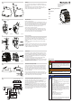
Mounting
ThiscomponentcanbesnappedonaTS35DINrail(Figure1a).
Itisremovedbyusingascrewdriveronthesnap-onfoot(asshown
inFigure1b).
Werecommendusinganendbracket(theWEW35/2,order
number1061210000)ateachendofeverycomponentgroup–es-
peciallywhentheapplicationissubjecttovibration.
Wire connection
Screwconnect(Figure2a)
Thisconnectionisdesignedforwirecross-sectionsfrom0.2to1.5
mm².Thestrippinglengthis8mm.APH0screwdriver(forexample,
SDKPH0,ordernumber9008470000)ora0.6x3.5slottedscrew-
driver(forexampleSD0.6x3.5x100,ordernumber9008330000)
shouldbeusedwithamax.tighteningtorqueof0.4Nm.
Tension-clampconnection(Figure2b)
Thisconnectionisdesignedforwirecross-sectionsfrom0.14to
1.5mm².Thestrippinglengthis8mm.Thetensionclampcanbe
openedandclosedusinga0.6x3.5slottedscrewdriver(forexam-
ple,theSD0.6x3.5x100,ordernumber9008330000).
Cross-connecting
Thenumberofcross-connectionscanbereducedbycuttingalong
cut-outlineAwithasuitabletool(suchastheKTZQV,order
number9002170000)orbybreakingoutindividualpolesalongcut-
outlineB.
Caution:Donotallowthecontactelementstobecomemisshap-
enordeformed!
Potentialsfromallveterminalpointscanbecross-connectedusing
theZQV1.5R6.4/...cross-connector.Thecross-connectorsmustbe
snappedinfullywheninserted.Simplyleveroutthecross-connec-
torwithascrewdriverinordertoremoveit.
Partition wall
Thepartitionisusedforvisuallyseparatingthecircuitsorforelec-
tricalisolationbetweenneighbouring,non-insulatedcross-connec-
tions.Byestablishingahigherinsulationbetweentwoterminals,it
isalsoidealasasafeisolationmechanismorforvoltagesgreater
than250V(Figure4a).
Acontinuouscross-connectioncanbemadebycuttingoutthe
breakpoints(cutalonglineA,asshowninFigure4b).
Iftwopartitionsarealignednexttoeachother,thecross-connection
pitchremainsthesame.TheWS12/6-typemarkers(ordernumber
1609900000)canthenbemounted.
Replacement of the relay or SSR
Thesecomponentsareremovedbymovingthetransparentlever
(asshowninFigure5a).Tomount,pressthecomponentintothe
baseuntilyouhearandseetheleversnapintopositionoverthe
component(Figure5b).Beforemounting,besuretopayattention
tothecoilvoltage(refertothemarkingonthebase)andthealign-
mentoftherelaylegs.
WhenyoureplaceanSSRwitharelay,besuretousetheprop-
eroutputcongurationaccordingtotheloadbeingswitched.These
productsweretestedwiththelistedaccessories.Theuseofother
relaysorSSRsisatyourownriskandresponsibility.
Connection assignments / Input control circuit
Theinputcontrolcircuitincludeselectroniccomponentswhichpro-
videprotectivecircuitryfortherelaycoilortheSSRinput.
Thecomponentswillagemorequicklyifoperatedcontinuouslyat
ambienttemperaturesabove50°C.
Forcontrolvoltages≤60V,theinputcontrolcircuitcontainsafree-
wheel/reverse-polarity-protecteddiode(fortheACrectier)anda
statusLED.
Forcontrolvoltagesgreaterthan60Vandformulti-voltageinputs
from24to230V,theinputcontrolcircuitalsocontainsavoltagedi-
vider.ThisallowstherelaycoilsorSSRinputstobeusedwithdif-
ferentnominalvoltages.
WeidmüllerInterfaceGmbH&Co.KG
Klingenbergstrasse16
32758Detmold
Germany
R.T.No.1278710000/00/03.11
1
2
3
4
5
6
Safety Notices
DANGER
Thefollowingnoticemustbeobservedinordertoensure
safeinstallationandoperationofthecomponents:
• Thiscomponentshouldonlybeinstalledbyatrained,
qualiedspecialistwhoisfamiliarwiththenationaland
internationalregulations,lawsandstandardsthatapply
totheregionofapplication.
WARNING
• Allvalidtechnicalrequirementsandoperationalnotic-
esmustbetakenintoaccountwheninstalling,commis-
sioningandservicingthedevice.
NOTE
Status LED
• ThestatusLEDdisplayontheinputcontrolcircuitcan
differfromthestateofthecontactcircuitinthefollow-
ingcases:
– whentherearewelded-togetherorbrokenswitch-
ingelements,
– whenthereisinterferenceorresidualvoltageson
thesignallines.
• Areductioninlightintensitymayresultwhentheambi-
enttemperaturesaregreaterthan50°C.
Protective circuitry for the contacts
• Arcingoccurswhenswitchinginductiveorcapacitive
loads;theseinuencetheelectricallifespanofthecon-
tacts.Werecommendprotectivecircuitryforthecon-
tactsinordertoprotectthecontactsandtoavoidcou-
plinginterferenceonotherlines.
UL approval
• Ambienttemperature:max+60°C
• Usecopperconductorsonly
• Foruseinpollutiondegree2
Pleaserefertotheproductdatasheetortheonlinecata-
logue(atwww.catalog.weidmueller.com)fortheproduct-
specictechnicalspecications.
û
AA
B
B
Figure1a Figure1b
0,14...1,5 mm
AWG 26...16
2
8 mm
B
A
û
X
8 mm
0,2...1,5 mm
AWG 24...16
2
0,4 Nm
Figure2bFigure2a
Figure5a
Figure5b
A
A
Figure4a Figure4b
AC input + RC fi lter
AC/DC input
DC input
A2
A1
NO
14
11
12
NC
COM
TRS
TOS
14
14
11
11
12 A1
A1
A2
A2