
User Documentation


26 2661740000/01/06-2020
Measuring
Measuring MOVs
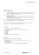
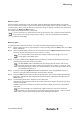
To measure an MOV component (Varistor), or an SPD comprising several metal oxide varistor internally:
Step 1 Decide if using the auto or manual detection mode by pressing either the AUTO button or the MOV
button respectively.
Step 2 Set the required constant current for the measurement (refer to Measurement screen section).
The current used can be selected from one of 0.1 mA, 0.5 mA, 1.0 mA.
It is normal to dene the clamping voltage of an MOV as Un @ 1 mA DC, so typically the
1.0 mA setting is the default option.
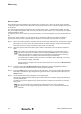
Step 3 If desired, enable the Log Measurement mode LOG mode (refer to Log screen section). A
check ✔ in the footer panel indicates this mode has been activated.
Step 4 Press the TEST button on the front panel of the instrument. The red high voltage LED will briey
illuminate to indicate that high voltage is being produced at the output terminal sockets (refer to
Safety section).
Step 5 The measured values will be displayed on the output panel.
Compare the measured values with the given table values in the chapter “Surge protection prod-
ucts from Weidmüller”.
The MOV component is defective if the measured value is outside of the minimum to maximum
range given.
For more information on measurement of MOV components, the user is referred to:
IEC 61643-331 Components for low-voltage surge protective devices – Part 331: Speci-
cation for metal oxide varistors (MOV).