
User Documentation


4 Module descriptions | Digital input and output modules IP67, PROFIBUS, 60mm, metal housing
242484950000/00/03.2016 Manual UR67-PROIFBUS
Voltage error on M12 sockets or sensor short circuit
Contact1 of each M12 socket contributes the voltage supply
with a 24V potential. This potential is generated from the
system/sensor supply U
S
and it is monitored.
In case of a sensor short circuit a sensor error is indicated.
Both channel indicators of the M12 socket ash red and a
diagnosis message for both channels is sent.
Overload of output drivers
The output drivers of the modules with output function will
send an error if they recognise an overload.
If both output channels of a M12 socket are ena-
bled during overload occurance, both channels
will be blocked even if only one of them is af-
fected. If only one channel is enabled during over-
load then only this one will be blocked on channel
error.
Blocked channels are being enabled and keep the
status "off" unless they are reset and set again by
the control.
The status indicator of the active ouput channel will ash red
in case of overload. If both output channels of a M12socket
are active during an overload both indicator LED will ash
red. An actuator error will be sent as diagnosis to the PROFI-
BUS master.
The overload error can be ltered by the „Surveillance Time-
out“ parameter. The setting of this parameter also applies to
channel, voltage and overload errors.
Error of actuator supply U
L
The voltage values of the actuator supply connections U
L
are
monitored overall and module-wise. An error will be reported
as soon as the value range 18V ... 30V is under or overun.
The indicator LED ashes red and an actuator supply error
will be sent as a diagnosis to the PROFIBUS master.
In case of an actuator supply error the output chan-
nel will be blocked if it was currently enabled. It
must be reset by the control as soon as the power
supply U
L
has normalised.
Error of system/sensor supply U
S
The voltage values of the system/sensor supply connections
U
S
are monitored overall. An error will be reported as soon as
the value range 18V ... 30V is under or overun.
The indicator LED U
S
ashes red and a sensor supply error
will be sent as a diagnosis to the PROFIBUS master.
This error has no effect on the outputs and will not be l-
tered but reported immediately.
Diagnosis via PROFIBUS-DP
If a UR67 module recognises an error status it will trigger a
diagnosis (e.g. with peripheral errors like overload, short cir-
cuit, underload).
Evaluation of alarms in STEP7
In STEP7 the application processing is disturbed by trigger-
ing a diagnosis and a diagnosis module is called up. The fol-
lowing modules are used:
Reason of alarm OB called up
Peripheral error (short circuit, overload, line brake,
undervoltage of a I/O module)
OB 82
Complete breakdown of the system OB 86
Due to the called up OB and its start information the rst
information about failure reason and failure type are already
delivered. More detailed information about the failure you
will nd in error OB82 by calling up the SystemFunction
SFC13 „DPNRM_DG“ (reading diagnosis data of a DP-slave)
or the SystemFunctionBlock SFB 54 „RALRM“ (reading ad-
ditional alarm info).
The CPU will change to operation status "STOP" if the called
up error OB is not available in the CPU.
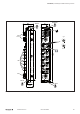
Diagnosis
Bit 7 6 5 4 3 2 1 0
Standard diagnosis
Byte 0
Station status 1
Byte 1
Station status 2
Byte 2
Station status 3
Byte 3
PROFIBUS address (station number) of the master
Byte 4
High-Byte of the ID number (in this case: 0E)
Byte 5
Low-Byte of the ID number (in this case: 94)
Device related diagnosis
Byte 6
0 0 0 0 0 0 1 0
Byte 7
Module
error
Actuator
error
Sensor
error
Error
U
S
Error
U
L
With respective error the corresponding error bit will be set in byte7.
Channel related diagnosis
Byte 8 0 1 0 0 0 0 1 0
Byte 9
Socket
8
Socket
7
Socket
6
Socket
5
Socket
4
Socket
3
Socket
2
Socket
1
In case of error on a M12 socket the corresponding error bit will be set.