
User Documentation
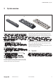
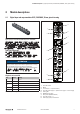

4 Module descriptions | Digital input and output modules IP67, PROFIBUS, 30mm, plastic housing
92484950000/00/03.2016 Manual UR67-PROIFBUS
PROFIBUS address
You can set the module's PROFIBUS address either using the
rotary switches or via the PROFIBUS-DP network. A value
between 1 and 99 (default 99) is possible using the rotary
switches, via the PROFIBUS-DP network you can choose a
value between 1 and 126.
The address set will be adopted during switching
on the power supply. For a change the power sup-
ply has to be interrupted temporarily.
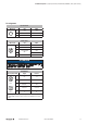
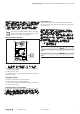
Setting the address manually
8
x10
x1
OUT
5
0
1
2
3
4
9
8
7
6
5
0
1
2
3
4
9
8
7
6
Rotary switches on the module
▶ Open the clear cover (crosshead srewdriver 2mm).
▶ Set the address using the rotary switches (unit position
above, decade below).
▶ Close the clear cover.
The address set will be adopted during the next switch-on of
the power supply.
Changing the address
▶ Set the new address as described above.
▶ Interrupt the power supply temporarily.
The new address set will be adopted during the next switch-
on of the power supply.
Setting the address via the network
Prior to this you have to set the rotary switches to "00". This
setting may not be changed during operation. You will nd a
detailed description in the manaul of your respective PROFI-
BUS-DP-master.
Data transfer rate
The data trasfer rate will be detected and set automatically
as soon as the module communicates with the master (auto
baud detection).
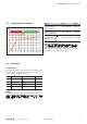
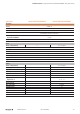
Process data and bit assignment
The PROFIBUS-DP telegram permits the transmission of
244bytes user data at maximum.
The UR67-PB-12-8DI-8-30K module can transmit one byte
(input only) .
The UR67-PB-12-8DIO-8-30K module uses – depending on
the conguration
– 8DI/8DO: one input byte and one output byte
– 8DI: one input byte
– 8DO: one output byte
Bit 7 6 5 4 3 2 1 0
M8 Input
Byte 0 8 7 6 5 4 3 2 1
M8 Output
Byte 0 8 7 6 5 4 3 2 1