
User Documentation

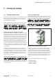


5.3 Attaching the markers
Attaching connection markers
The module as well as the connections can be labelled using
the markers. This ensures clear allocation even on mainte-
nance work.
▶ Press the labelled marker into the corresponding fixture.
▶ For reversal lever out the marker carefully using a screw
driver (2.5 or 3mm).
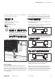
5.4 Adjusting the PROFIBUS address
You will nd the description how to adjust the address in the
respective module description (see Chapter4).
5.5 Wiring
WARNUNG
Dangerous contact voltage!
▶ Carry out assembly and wiring work only
when the power supply is disconnected.
▶ Make sure that the place of installation
has been disconnected from the power
supply!
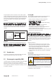
Once the module has been mechanically installed, the wiring
can be carried out in accordance with the wiring plan.
Ensure compliance with the minimum permis-
sible cable bending radius.
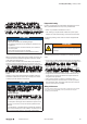
5.6 Insulation test
Insulation tests have to be done according to the national
regulations, in any case necessarily before each commission-
ing.
ACHTUNG
The product can be destroyed by too
high test voltage!
Please note during insulation test:
– within one channel the test voltage bet-
ween 24V and GND must not exceed
30V!*
– A maximum test voltage of 500V can be
applied tho all other connection points.
* We recommend to short-circuit 24V and GND on the sup-
ply connector.
5 Installation | Attaching the markers
312484950000/00/03.2016 Manual UR67-PROIFBUS